


This is the first version of the FM100 MODULAR CHASSIS FROM SIEMENS BLAUPUNKT.
This here was using the Memotronic Tuning system based on Motorola tuning memory.
 The CHASSIS FM100 is a modular chassis and introduces severals improvements compared to earlyer types:
SSVD TECH AND
more integration in video stages and if stages.
Phasing out the Thyristor technology for line stages.
The CHASSIS FM100 delivers a totally uncommon Frame deflection system,
Plus the E/W Correection circuit uses the same Technology.
It's a system called S.S.V.D. which stays for Synchronized Switched Vertical Deflection.
The system is highly reliable and does dissipate energy like linear amplifier types like A class or AB class Types and should
 not be confused with D Class amplifier.
Abstract:
In a switched vertical deflection circuit, two SCR switches couple horizontal retrace pulses to a capacitor. A modulator couples pulse width modulated gating pulses to the SCR's. The SCR's couple to the capacitor successively smaller portions of the horizontal retrace pulses during a first part of the vertical trace interval and successively larger portions during a second part for developing in a vertical deflection winding a sawtooth vertical deflection current. The modulator couples gating pulses to one of the SCR's during the vertical retrace interval for substantially loading the horizontal deflection circuit during the vertical retrace interval for preventing undesired oscillations within the horizontal deflection circuit.
What is claimed is:
1. A switched vertical deflection system comprising:a horizontal deflection circuit including first means for generating horizontal rate energy signals;
a vertical deflection winding;
energy storage capacitance means coupled to said vertical deflection winding;
first and second switching means coupled to said first means and said energy storage capacitance means; and
second means coupled to said first and second switching means for switching conductive states of both of said switching means for coupling successively smaller portions of said horizontal rate energy signals to said energy storage capacitancemeans during a first part of a vertical trace interval and successively larger portions of said horizontal rate energy signals during a second part of said vertical trace interval for developing a vertical deflection current in said vertical deflectionwinding during said vertical trace interval,
said second means causing said first switching means to conduct during a vertical retrace interval for coupling substantial portions of said horizontal rate energy signals to said energy storage capacitance means during said vertical retraceinterval for preventing undesired oscillations within said horizontal deflection circuit.
3. A system according to claim 2 wherein said second means includes transformer means for coupling said first signals to said first switching means.
4. A system according to claim 3 wherein said first switching means comprises a silicon controlled rectifier, a secondary winding of said transformer means coupled between the gate and cathode electrodes of said silicon controlled rectifier.
5. A system according to claim 2 including vertical signal means coupled to said second means for generating a vertical rate signal for modulating said first and second signals at a vertical rate.
6. A system according to claim 5 wherein said vertical signal means includes first circuitry for generating a component of said vertical rate signal that inhibits conduction of said second switching means during said vertical retrace interval.
7. A system according to claim 6 wherein said first circuitry comprises an RC differentiating circuit.
8. A system according to claim 7 wherein the time constant of said differentiating circuit is selected to provide a duration for said component of said vertical rate signal substantially equal to said vertical retrace interval.9. In a television receiver including a horizontal deflection circuit comprising a horizontal deflection generator and a horizontal output transformer, a switched vertical deflection circuit comprising:
a vertical deflection winding;
energy storage capacitance means coupled to said vertical deflection winding;
first and second controllable switches coupled to said capacitance means and to respective secondary windings of said horizontal output transformer for coupling horizontal retrace signals to said capacitance means; and
a modulator coupled to said first and second controllable switches and responsive to a source of vertical rate signals for providing to said controllable switches during said vertical trace interval horizontal rate signals modulated at a verticalrate for varying the amount of each horizontal retrace signal coupled to said capacitance means for generating a vertical deflection current in said vertical deflection winding during said vertical trace interval, said switched vertical deflectioncircuit substantially loading said horizontal deflection circuit at the beginning and end of said vertical trace interval,
said modulator providing signals to said first controllable switch during said vertical retrace interval for coupling said horizontal retrace signals to said capacitance means during said vertical retrace interval for substantially loading saidhorizontal deflection circuit during said retrace interval for preventing undesired oscillations within said horizontal deflection circuit.
10. A circuit according to claim 9 wherein said vertical rate signals cause said modulator to provide for conduction of said first controllable switch during said vertical retrace interval and for inhibiting conduction of said second controllable swith during said vertical retrace interval.
 Description:
BACKGROUND OF THE INVENTION
This invention relates to switched vertical deflection circuits for a television receiver.
In a switched vertical deflection circuit of the type disclosed in U.S. Patent Application Ser. No. 595,809, now U.S. Pat. No. 4,048,544, filed July 11, 1975, by Peter Eduard Haferl, entitled, SWITCHED VERTICAL DEFLECTION SYSTEM, horizontalrate energy, in the form of horizontal retrace pulses from a horizontal output transformer of a horizontal deflection circuit, charges a capacitor in parallel with a vertical deflection winding. A first switch, such as an SCR, couples successivelysmaller portions of the horizontal rate energy to the capacitor during a first part of the vertical trace interval and a second switch, such as another SCR, couples successively larger portions of the horizontal rate energy during a second part of thevertical trace interval. The voltage across the capacitor is integrated by the vertical deflection winding into a sawtooth vertical deflection current. The conduction of the two SCR switches is controlled by horizontal rate pulse width modulated pulsescoupled from a modulator to the SCR gate electrodes.
At the start of vertical retrace, the second SCR switch which had previously been conducting is maintained in cutoff. The vertical deflection winding and the capacitor form a resonant retrace circuit. A disconnect diode coupled to the gate ofthe first SCR switch is reversed biased, maintaining the SCR in cutoff independent of the gating pulses generated by the modulator. With both SCR's nonconducting, resonant retrace of the current in the vertical deflection winding is accomplished. Atthe start of the subsequent vertical trace interval, the disconnect diode is no longer reverse biased. Pulse width modulated gating pulses to the first SCR enable the SCR to couple the horizontal retrace pulses to the capacitor for generating thesawtooth deflection current in the vertical deflection winding.
Both SCR's conduct relatively large amounts of current at the beginning and end of the vertical trace interval, respectively. Neither SCR conducts during the vertical retrace interval. Accordingly, loading of the horizontal deflection circuitby the switched vertical deflection circuit will be greatest at the beginning and end of the vertical trace interval, with substantially no loading occurring during the vertical retrace interval. Such load interruption during the vertical retraceinterval may cause undesirable modulation of the horizontal deflection current and undesirable oscillations within the horizontal deflection circuit. These oscillations may appear, for example, in the "S" shaping capacitor or in the horizontal outputtransformer windings as the load impedance of the vertical deflection circuit abruptly changes. It is, therefore, desirable to provide a switched vertical deflection circuit in which undesirable oscillations within the horizontal deflection circuit areprevented.
SUMMARY OF THE INVENTION
A switched vertical deflection circuit comprises a horizontal deflection circuit including apparatus for generating horizontal rate energy signals, a vertical deflection winding, an energy storage capacitance, first and second switches and aswitching circuit coupled to the switches. The switching circuit switches the conductive states of the switches for coupling successively smaller portions of the horizontal rate energy signals to the energy storage capacitance during a first part of thevertical trace interval and successively larger portions during a second part for developing a vertical deflection current in the vertical deflection winding during the vertical trace interval. The switching circuit causes the first switch to conductduring the vertical retrace interval for coupling substantial portions of the horizontal rate energy signals to the energy storage capacitance during the vertical retrace interval for preventing undesired oscillations within the horizontal deflection circuit.1. In a television receiver,
having means (1, 2) coupling out a portion of the energy delivered by the horizontal deflection circuit during line flyback or retrace;
a vertical deflection output stage (V) including deflection means (LV1, LV2) and a charge capacitor element (C);
and a sawtooth wave generator (S), which controls application of the coupled-out energy derived from the horizontal deflection circuit to the vertical deflection means (LV1, LV2), a method to control vertical deflection
comprising, in accordance with the invention, the step of
additionally controlling application of the energy to the vertical deflection means by the sawtooth wave generator during the vertical flyback or retrace interval by reversely re-charging said capacitor element during said interval.
2. Method according to claim 1, wherein the re-charging step is carried out continuously.
3. Method according to claim 1, wherein the re-charging step is carried out linearly.
4. Method accordi
 ng to claim 1, wherein the vertical deflection output stage includes, vertical deflection coil elements (LV1, LV2) and forming with said charge capacitor element (C) said deflection means, a feedback resistor element (R) and a vertical correction circuit element (4), said charge capacitor element and said other elements being connected to form a parallel oscillatory circuit;
 said method including the step of controlling the damping of the parallel oscillatory circuit by controlling the relative parameters of said elements.
5. In a television receiver, a vertical deflection system including means (1, 2) coupling out a portion of the energy delivered by the horizontal deflection circuit during line flyback or retrace;
a vertical deflection output stage (V) including vertical deflection means (LV1, LV2);
and a sawtooth wave generator (S) controlling application of the coupled-out energy to the vertical deflection means during the flyback interval
and wherein, in accordance with the invention,
the time constant (τS) of the sawtooth wave generator (S) is longer than the time constant (τV) of the vertical deflection output stage (V).
6. Vertical deflection system according to claim 5, wherein the time constant of the vertical deflection output stage is about twice as long as that of the sawtooth wave generator (S).
7. Vertical deflection system according to claim 5, wherein the ratio of time constants (τS /τV) is between about 1.5 to 2.5.
8. Vertical deflection system according to claim 5, wherein the vertical deflection output stage (V) includes a charge capacitor element (C), vertical deflection coil elements (LV1, LV2) forming said vertical deflection means, a feedback resistor element (R) and a vertical correction circuit element (4), said elements being connected to form a parallel oscillatory circuit;
and wherein said oscillatory circuit is a damped oscillatory circuit.
9. Vertical deflection system according to claim 8, wherein the elements of said oscillatory circuit are dimensioned to provide a time constant which is about half of the time constant of the sawtooth wave generator (S) and is in the order of about 0.5 ms.
Description:
The present invention relates to a deflection circuitry for television receivers, and more particularly to a deflection circuit in which energy contained in the horizontal flyback is used in the vertical deflection system.
Video scanning in television receivers is effected, as well known, by a vertical deflection circuit. A pulse generator is synchronized by pulses included in the video signal. The pulses are then applied over a pulse generator, a driver and an output stage to deflection systems, usually deflection coils.
Various types of solid-state circuits have been proposed; for example, U.S. Pat. No. 4,048,544 describes a transistorized vertical deflection circuit with additional circuitry to stabilize the pulses. The time constant of the pulse generator and of the driver stage of such circuits is less than the time constant of the output or final power stage of the vertical deflection circuit. Such vertical deflection circuits have some disadvantages, particularly in that the transistors are operated at high voltages which may result in flash-over and thus damage or destruction of the transistor. The power required to control the final output transistors is already substantial and thus the overall operating efficiency of such a vertical deflection circuit is low.
In earlier developments, a vertical deflection circuitry was proposed which avoids some of the disadvantages of this transistorized circuit; in this earlier circuit, a portion of the energy contained in the horizontal flyback is coupled out and is directly utilized in order to supply current for the vertical deflection coils. To control application of current, a controlled sawtooth wave generator is connected to the final output stage of the vertical deflection circuit, the sawtooth wave generator having a short retrace or flyback time. These vertical deflection circuits also have some disadvantages. The energy derived for vertical deflection is obtained from the horizontal flyback; thus, changes in loading in the vertical deflection circuitry affect the horizontal output stage. The vertical deflection circuit is subject to substantial changes in loading during the vertical flyback or retrace since, in accordance with the previously known circuit, the vertical deflection circuit is not controlled during the vertical flyback or retrace. The lack of control of the vertical deflection circuit causes abrupt changes in loading which result in undesired spurious oscillations in the vertical output stage. These oscillations can so feed back or react on the horizontal output stage that the horizontal flyback pulses are overloaded, the vertical stage starts to oscillate, and high voltages may occur therein during the vertical flyback. This, necessarily, degrades the image quality of the reproduced video picture. High-voltage flash-over may occur and electronic components, particularly solid-state semiconductor elements can be destroyed thereby.
It is an object of the present invention to provide a vertical deflection circuit for television receivers, which has the advantages of utilizing a portion of the energy contained in the horizontal deflection circuit during horizontal flyback without causing abrupt changes in loading on the horizontal output stage and preventing undesired spurious and uncontrolled oscillation of the vertical output stage.
SUBJECT MATTER OF THE PRESENT INVENTION
Briefly, the sawtooth wave generator which controls charging of a charge capacitor of the vertical output stage is controlled to in turn control the charge on the capacitor also during vertical retrace; in accordance with a feature of the invention, this control is obtained by so arranging and relatively matching the time constants of the sawtooth wave generator and of the parallel oscillatory circuit formed by the vertical deflection coils of the T.V. receiver and the charge capacitor that the time constant of the vertical deflection output stage is less, preferably about half that of the time constant of the sawtooth wave generator. This matching can be obtained by so selecting the values of the components of the vertical deflection output stage that the resulting oscillatory circuit formed by the capacitor, resistance elements in the circuit, and the vertical deflection output stage form a damped oscillatory circuit.
The invention will be described by way of example with reference to the accompanying drawings, wherein the single FIGURE is a schematic diagram of a vertical deflection output stage in which the method of the present inv ention is carried out, and utilizing the system thereof.
A horizontal deflection output stage 1 is connected to a horizontal output transformer 2 which has coupling windings W 1 and W 2 to derive a portion of the energy contained in the line retrace. This energy is stored in the inductances L 1 and L 2 and then applied through thyristors Th 1 and Th 2 to a charge capacitor C. A control circuit 3 is provided triggering the thyristors Th 1 and Th 2 in such a manner that the charge capacitor C is positively charged during the first half of the video scan and negatively during the second half of the video scan. The charge capacitor C is discharged through the vertical deflection coils L V1 and L V2 , a vertical correction circuit 4 for vertical correction and a feedback resistor R. The voltage drop across feedback resistor R is fed back to the control circuit 3 in order to ensure exact triggering of the thyristors Th 1 and Th 2 and to control the desired deflection current.
Positive deflection current is obtained during the first half of the video scan by the triggered thyristor Th 1 ; negative deflection current is derived during the second half of the video scan by the triggered thyristor Th 2 . The thyristors Th 1 and Th 2 can be triggered during a portion of the video scan simultaneously to result in a linear deflection and provide overlapping, opposite deflection currents.
The control circuit 3, together with the thyristors Th 1 and Th 2 , and the inductances L 1 and L 2 , forms a sawtooth wave generator S. The vertical deflection output stage V is formed of the vertical deflection coils L V1 , L V2 , the vertical correction circuit 4, the charge capacitor C and the feedback resistor R. As can be seen from the FIGURE, the capacitor C on the one hand, and the deflection coils, the correction circuit 4 and the resistor R on the other hand form a parallel oscillatory circuit.
The circuit, as far as the diagram is concerned, is known. Uncontrolled, undesired and spurious oscillations in the horizontal output stage can be avoided, in accordance with the invention, by reverse re-charging the capacitor C also during the vertical retrace interval. This re-charging of the capacitor C preferably is carried out continuously and desirably linearly. The controlled re-charging of the capacitor C can be readily obtained by arranging the relative values of the components in the sawtooth wave generator S and in the vertical output stage V such that the time constant τ S of the sawtooth wave generator is longer than the time constant τ V of the vertical deflection output stage. Mathematically: τ S >τ V (1)
preferably, the quotient of the time constants should be between 1.5 and 2.5, most desirably about 2, mathematically: 1.5>τ S /τ V <2.5 (2)
if the time constants of the respective circuits are properly arranged, the thyristors Th 1 and Th 2 can be precisely triggered also during the short time interval of the vertical flyback or retrace. Due to the short time constant, the vertical deflection circuit can then follow the control from the control circuit 3 exactly; the voltage dropped across the feedback resistor R will permit precise triggering, with respect to time, of the thyristors Th 1 and Th 2 also during the vertical flyback. In the first half of the video scan, the thyristor Th 2 is triggered; in the second half, thyristor Th 1 is triggered. This ensures linear flyback.
The time constant τ V is essentially determined by the vertical deflection coils L V1 , L V2 , the correction circuit 4, and the feedback resistor R which, together with the capacitor C, form a parallel oscillatory circuit. A short time constant corresponds to high damping of this parallel oscillatory circuit. Thus, in accordance with a feature of the present invention, by suitably arranging the ratio of the time constants, the parallel oscillatory circuit will not start undesired uncontrolled oscillations which could interfere with image reproduction quality, or proper operation of the components of the T.V. receiver. The ratio of the time constants can be selected by suitable adjustment of t he damping of the oscillatory circuit.
The vertical deflection circuit has an essentially continuous, uniform and even power requirement. This avoids abrupt changes in loading during the vertical retrace. Excessive over-compensation of horizontal flyback pulses, and resulting high voltages which may lead to undesired distortion of the reproduced image and possibly to damage or destruction of components of the video system are avoided. The vertical deflection circuitry, as described, can be readily manufactured and has high operating reliability. The efficiency is high and the power requirement is low.
Various changes and modifications may be made within the scope of the inventive concept.
In a typical T.V. receiver using vertical deflection coils of 20 millihenry inductance, a suitable time constant τ V is 0.5 ms. In such a circuit, the resistor R can have a value 1 Ω capacitor C a value of 1.5 μF. and the reflected impedance of correction circuit 4 a value of 1 Ω.
The sawtooth wave generator has a time constant of 1 ms, providing for a slow rise time for 20 milliseconds. The circuit 3 is well known and described in U.S. Pat. No. 4,048,544.
Video scanning in television receivers is effected, as well known, by a vertical deflection circuit. A pulse generator is synchronized by pulses included in the video signal. The pulses are then applied over a pulse generator, a driver and an output stage to deflection systems, usually deflection coils.
Various types of solid-state circuits have been proposed; for example, U.S. Pat. No. 4,048,544 describes a transistorized vertical deflection circuit with additional circuitry to stabilize the pulses. The time constant of the pulse generator and of the driver stage of such circuits is less than
 the time constant of the output or final power stage of the vertical deflection circuit. Such vertical deflection circuits have some disadvantages, particularly in that the transistors are operated at high voltages which may result in flash-over and thus damage or destruction of the transistor. The power required to control the final output transistors is already substantial and thus the overall operating efficiency of such a vertical deflection circuit is low.
 In earlier developments, a vertical deflection circuitry was proposed which avoids some of the disadvantages of this transistorized circuit; in this earlier circuit, a portion of the energy contained in the horizontal flyback is coupled out and is directly utilized in order to supply current for the vertical deflection coils. To control application of current, a controlled sawtooth wave generator is connected to the final output stage of the vertical deflection circuit, the sawtooth wave generator having a short retrace or flyback time. These vertical deflection circuits also have some disadvantages. The energy derived for vertical deflection is obtained from the horizontal flyback; thus, changes in loading in the vertical deflection circuitry affect the horizontal output stage. The vertical deflection circuit is subject to substantial changes in loading during the vertical flyback or retrace since, in accordance with the previously known circuit, the vertical deflection circuit is not controlled during the vertical flyback or retrace. The lack of control of the vertical deflection circuit causes abrupt changes in loading which result in undesired spurious oscillations in the vertical output stage. These oscillations can so feed back or react on the horizontal output stage that the horizontal flyback pulses are overloaded, the vertical stage starts to oscillate, and high voltages may occur therein during the vertical flyback. This, necessarily, degrades the image quality of the reproduced video picture. High-voltage flash-over may occur and electronic components, particularly solid-state semiconductor elements can be destroyed thereby.
It is an object of the present invention to provide a vertical deflection circuit for television receivers, which has the advantages of utilizing a portion of the energy contained in the horizontal deflection circuit during horizontal flyback without causing abrupt changes in loading on the horizontal output stage and preventing undesired spurious and uncontrolled oscillation of the vertical output stage.
SUBJECT MATTER OF THE PRESENT INVENTION
Briefly, the sawtooth wave generator which controls charging of a charge capacitor of the vertical output stage is controlled to in turn control the charge on the capacitor also during vertical retrace; in accordance with a feature of the invention, this control is obtained by so arranging and relatively matching the time constants of the sawtooth wave generator and of the parallel oscillatory circuit formed by the vertical deflection coils of the T.V. receiver and the charge capacitor that the time constant of the vertical deflection output stage is less, preferably about half that of the time constant of the sawtooth wave generator. This matching can be obtained by so selecting the values of the components of the vertical deflection output stage that the resulting oscillatory circuit formed by the capacitor, resistance elements in the circuit, and the vertical deflection output stage form a damped oscillatory circuit.
The invention will be described by way of example with reference to the accompanying drawings, wherein the single FIGURE is a schematic diagram of a vertical deflection output stage in which the method of the present inv
ention is carried out, and utilizing the system thereof. A horizontal deflection output stage 1 is connected to a horizontal output transformer 2 which has coupling windings W 1 and W 2 to derive a portion of the energy contained in the line retrace. This energy is stored in the inductances L 1 and L 2 and then applied through thyristors Th 1 and Th 2 to a charge capacitor C. A control circuit 3 is provided triggering the thyristors Th 1 and Th 2 in such a manner that the charge capacitor C is positively charged during the first half of the video scan and negatively during the second half of the video scan. The charge capacitor C is discharged through the vertical deflection coils L V1 and L V2 , a vertical correction circuit 4 for vertical correction and a feedback resistor R. The voltage drop across feedback resistor R is fed back to the control circuit 3 in order to ensure exact triggering of the thyristors Th 1 and Th 2 and to control the desired deflection current.
Positive deflection current is obtained during the first half of the video scan by the triggered thyristor Th 1 ; negative deflection current is derived during the second half of the video scan by the triggered thyristor Th 2 . The thyristors Th 1 and Th 2 can be triggered during a portion of the video scan simultaneously to result in a linear deflection and provide overlapping, opposite deflection currents.
The control circuit 3, together with the thyristors Th 1 and Th 2 , and the inductances L 1 and L 2 , forms a sawtooth wave generator S. The vertical deflection output stage V is formed of the vertical deflection
coils L V1 , L V2 , the vertical correction circuit 4, the charge capacitor C and the feedback resistor R. As can be seen from the FIGURE, the capacitor C on the one hand, and the deflection coils, the correction circuit 4 and the resistor R on the other hand form a parallel oscillatory circuit. The circuit, as far as the diagram is concerned, is known. Uncontrolled, undesired and spurious oscillations in the horizontal output stage can be avoided, in accordance with the invention, by reverse re-charging the capacitor C also during the vertical retrace interval. This re-charging of the capacitor C preferably is carried out continuously and desirably linearly. The controlled re-charging of the capacitor C can be readily obtained by arranging the relative values of the components in the sawtooth wave generator S and in the vertical output stage V such that the time constant τ S of the sawtooth wave generator is longer than the time constant τ V of the vertical deflection output stage. Mathematically: τ S >τ V (1)
preferably, the quotient of the time constants should be between 1.5 and 2.5, most desirably about 2, mathematically: 1.5>τ S /τ V <2.5 (2)
if the time constants of the respective circuits are properly arranged, the thyristors Th 1 and Th 2 can be precisely triggered also during the short time interval of the vertical flyback or retrace. Due to the short time constant, the vertical deflection circuit can then follow the control from the control circuit 3 exactly; the voltage dropped across the feedback resistor R will permit precise triggering, with respect to time, of the thyristors Th 1 and Th 2 also during the vertical flyback. In the first half of the video scan, the thyristor Th 2 is triggered; in the second half, thyristor Th 1 is triggered. This ensures linear flyback.
The time constant τ V is essentially determined by the vertical deflection coils L V1 , L V2 , the correction circuit 4, and the feedback resistor R which, together with the capacitor C, form a parallel oscillatory circuit. A short time constant corresponds to high damping of this parallel oscillatory circuit. Thus, in accordance with a feature of the present invention, by suitably arranging the ratio of the time constants, the parallel oscillatory circuit will not start undesired uncontrolled oscillations which could interfere with image reproduction quality, or proper operation of the components of the T.V. receiver. The ratio of the time constants can be selected by suitable adjustment of t
 he damping of the oscillatory circuit.
 The vertical deflection circuit has an essentially continuous, uniform and even power requirement. This avoids abrupt changes in loading during the vertical retrace. Excessive over-compensation of horizontal flyback pulses, and resulting high voltages which may lead to undesired distortion of the reproduced image and possibly to damage or destruction of components of the video system are avoided. The vertical deflection circuitry, as described, can be readily manufactured and has high operating reliability. The efficiency is high and the power requirement is low.
Various changes and modifications may be made within the scope of the inventive concept.
In a typical T.V. receiver using vertical deflection coils of 20 millihenry inductance, a suitable time constant τ V is 0.5 ms. In such a circuit, the resistor R can have a value 1 Ω capacitor C a value of 1.5 μF. and the reflected impedance of correction circuit 4 a value of 1 Ω.
The sawtooth wave generator has a time constant of 1 ms, providing for a slow rise time for 20 milliseconds. The circuit 3 is well known and described in U.S. Pat. No. 4,048,544.
SIEMENS BILDMEISTER FC524 (7 667 279) CHASSIS FM100 Switched vertical deflection system SSVD CIRCUIT THEORY EXPLANATION :
CHASSIS FM100
First and second controllable switching stages are respectively coupled between a source of horizontal retrace pulses and a capacitor connected across a vertical deflection winding. A modulator is coupled to the switching stages for controlling the timing of conduction thereof relative to the timing of the horizontal retrace pulses. One switching stage charges the capacitor in one polarity with pulses of current of gradually decreasing amplitude and duration during a first portion of the vertical trace interval and the other switching stage charges the capacitor in the opposite polarity with pulses of current of gradually increasing amplitude and duration during a second portion of the vertical trace interval. The capacitor supplies scanning current of first and second polarities to the vertical deflection winding during respective first and second portions of each vertical trace interval.
1. In a deflection system for cathode ray tubes, said deflection system of the type including a horizontal deflection circuit for deflecting an electron beam of said cathode ray tube in a horizontal direction in response to a horizontal deflection wave, a vertical deflection circuit comprising:
a vertical deflection winding responsive to a sawtooth current therethrough for deflecting said electron beam of said cathode ray tube in a vertical direction; and
means for applying successively smaller portions of the energy of said horizontal deflection wave during one interval of said vertical deflection and successively greater portions of said energy of said horizontal deflection wave during a second interval of said vertical deflection to said vertical deflection circuit for producing all of said sawtooth current in said vertical deflection winding, said first and second intervals occurring during the trace portion of each vertical deflection interval.
2. A vertical deflection circuit according to claim 1 wherein said means include controllable switches coupled to said horizontal deflection circuit and to said vertical deflection circuit for providing a current path for said horizontal retrace pulses therebetween. 3. A vertical deflection circuit according to claim 2 wherein a capacitor is coupled in parallel with said vertical deflection winding and to said controllable switches for being charged by said horizontal retrace pulses through said controllable switches and for supplying said sawtooth current in said vertical deflection winding. 4. A vertical deflection circuit according to claim 3 wherein first and second inductances are respectively coupled to first and second of said controllable switches and to said capacitor to form first and second series resonant circuits for charging said capacitor with said horizontal retrace pulse energy. 5. A vertical deflection circuit according to claim 4 wherein said resonant frequency of said first and second series resonant circuits is less than said horizontal rate frequency. 6. A vertical deflection circuit according to claim 5 wherein the resonant frequency of said capacitor in parallel with said vertical deflection winding has a period substantially equal to twice the vertical deflection circuit retrace interval. 7. A vertical deflection circuit according to claim 6 wherein said horizontal deflection retrace pulses are obtained from transformer windings in said horizontal deflection circuit coupled to said first and second controllable switching means. 8. A vertical deflection circuit according to claim 7 wherein modulator means responsive to vertical and horizontal deflection rate signals produce first and second trains of horizontal rate pulses the leading edges of which are successively and respectively delayed from and advanced toward the leading edge of said horizontal deflection retrace pulses and coupled to said first and second controllable switches for respectively controlling the conduction thereof. 9. A vertical deflection circuit according to claim 8 wherein said modulator
means produces said first and second trains of horizontal rate pulses which overlap during said vertical deflection interval. 10. A switched vertical deflection system comprising: a first series circuit including first and second switches, first and second sources of horizontal deflection rate voltage and first and second inductors;
a capacitor;
a second series circuit including said first switch, said first source of horizontal rate voltage, said first inductor and said capacitor;
a third series circuit including said second switch, and second source of horizontal rate voltage, said second inductor and said capacitor;
modulator means responsive to horizontal and vertical deflection rate signals for producing overlapping series of respective increasing and decreasing width horizontal rate pulses during each vertical deflection cycle respectively coupled to said first and second switches for controlling the conduction thereof for charging said capacitor to a first polarity through said second series circuit and to a second polarity through said third series circuit, said first series circuit conducting current of first and second polarities from said second and third series circuits such that only the amplitude difference between said first and second currents charges said capacitor when said pulses overlap; and
a vertical deflection winding coupled to said capacitor for providing a discharge path therefor for producing a substantially linear sawtooth alternating current in said deflection winding during each vertical deflection cycle.
11. A switched vertical deflection system for producing a sawtooth current in a vertical deflection winding, comprising:
a first series circuit including a first switch, a first source of horizontal retrace pulses, a first inductor and capacitor, said first source of horizontal retrace pulses being poled to cause current to flow in a direction to charge said capacitor in a first polarity direction, said first inductor and said capacitor being tuned to a frequency lower than the frequency of said horizontal retrace pulses;
a second series circuit including a second switch, a second source of horizontal retrace pulses, a second inductor and said capacitor, said second source of horizontal retrace pulses being poled to cause current to flow in a direction to charge said capacitor in a second polarity direction, said second inductor and said capacitor being tuned to a frequency lower than the frequency of said horizontal retrace pulses;
a vertical deflection winding coupled in parallel with said capacitor to form a parallel resonant circuit having a period substantially equal to twice the desired vertical retrace interval;
a source of signals having a frequency equal to the desired vertical deflection rate;
a modulator coupled to receive said horizontal retrace pulses and to said source of signals having a frequency equal to said desired vertical deflection rate for producing first and second sets of timing pulses, said first set of timing pulses occurring during the first half of said sawtooth current interval and having leading edges which occur increasingly later than the leading edges of said retrace pulses, said second set of timing pulses occurring during the second half of said sawtooth current interval and having leading edges which occur increasingly closer to the leading edges of said retrace pulses; and
means coupling said first and second sets of timing pulses to said first and second switches, respectively, for initiating conduction of current through said switches at the time of said leading edges of said timing pulses during said sawtooth current interval.
Description:
BACKGROUND OF THE INVENTION This invention relates to vertical deflection circuits and more particularly to switched mode vertical deflection circuits.
Most vertical deflection systems for television receiver use include linear amplifiers for amplifying a sawtooth voltage wave. The output stages in such systems may use single-ended or push-pull circuit configurations for driving a sawtooth of current through the vertical deflection winding. Measurements have shown that the vertical deflection output stage dissipates power in amounts which in some cases may be up to twice or more of the power consumed by the deflection winding.
More efficient vertical deflection circuits have been proposed utilizing class-D operated amplifier output circuits. In a class-D amplifier the output transistors are operated as switches, and since the transistors usually are either nonconducting or saturated when so operated, the power dissipation in the transistors is reduced. To achieve the required vertical rate scanning current waveform, it is common to pulse-width modulate a higher frequency signal, such as the horizontal rate signal or a multiple thereof, at the vertical deflection rate and use these pulse-width modulated signals to drive the class-D output stages. To remove the horizontal rate component from the vertical scanning current sometimes it is necessary to utilize filter networks which consume a relatively large amount of power, thereby offsetting the advantages of a class-D amplifier to some extent.
Another serious consideration in the use of class-D amplifiers is the minimizing of crossover distortion. Crossover distortion occurs when the scanning current sawtooth waveform is not linear when it passes through zero and reverses polarity at the middle of the vertical trace interval. Such distortion resulting from the nonlinear current manifests itself as an increased intensity horizontal bar across the center of the viewing screen. In other situations in which the class-D circuits produce a horizontal rate triangular current component on the vertical scanning current a diagonal line may appear on the viewing screen.
SUMMARY OF THE INVENTION
A vertical deflection circuit includes switches which are controlled for applying successively smaller portions of the horizontal retrace pulse energy during one portion of the vertical deflection cycle and successively greater portions of the horizontal retrace pulse energy during another portion of the vertical deflection cycle to the vertical deflection winding for developing a sawtooth current therein.
A more complete description of the invention together with a description of additional advantages thereof is given in the following description in conjunction with the accompanying drawing of which:
FIG. 1 is a schematic and block circuit diagram of a switched vertical deflection system embodying the invention;
FIGS. 2a-2h illustrate waveforms obtained at various points in the system of FIG. 1;
FIG. 3 is a more detailed schematic and block circuit diagram of a switched vertical deflection system embodying the invention;
FIGS. 4a-4c illustrate waveforms obtained at various points in the circuit of FIG. 3;
FIG. 5 is a detailed block and schematic circuit diagram of another switched vertical deflection system embodying the invention; and
FIGS. 6a-6f illustrate waveforms obtained at various points in the circuit of FIG. 5.
DESCRIPTION OF THE INVENTION
FI
 G. 1 shows a switched mode vertical deflection circuit which, for example, may be incorporated in a television receiver. Horizontal sync pulses 5 from a sync separator, not shown, are coupled to an input terminal 6 of a horizontal deflection generator 7. Horizontal deflection generator 7 may be any suitable type for supplying horizontal deflection current to a horizontal deflection winding 11 mounted adjacent to a cathode ray tube 10 as well as supplying horizontal rate pulses for various functions within a television receiver. A primary winding 8a of a horizontal output and high voltage transformer 8 receives energy from generator 7. A tertiary winding 8d of transformer 8 supplies retrace pulses to a high voltage multiplier and rectifier assembly 9 which provides a high DC voltage to the ultor terminal of cathode ray tube 10.
 On the secondary side of transformer 8 there are serially connected an SCR 13, a secondary winding 8b providing horizontal retrace pulses of approximately 80 volts, an inductance 14, an inductance 16, a second secondary winding 8c providing horizontal retrace pulses of approximately 80 volts and a second SCR 17. The anode of SCR 13 and the cathode of SCR 17 are grounded. The junction of inductances 14 and 16 is coupled through a capacitor 15 to ground and also through a vertical deflection winding 18 and a current sampling feedback resistor 19 to ground. The connections from either side of vertical deflection winding 18 to a vertical sawtooth generator 20 provide feedback for purposes to be described in conjunction with FIGS. 3 and 5.
Vertical deflection rate sync pulses 21 also derived from the sync separator are coupled to an input terminal 22 of the vertical sawtooth generator 20 to synchronize the operation thereof. Output signals obtained from vertical sawtooth generator 20 are coupled to a modulator 23. A source of direct current 12 is coupled to horizontal generator 7, vertical sawtooth generator 20 and modulator 23 and supplies operating current thereto.
Horizontal rate pulses obtained from a winding 8e of horizontal transformer 8 are also coupled to modulator 23. Output signals obtained from modulator 23 are coupled through a terminal 24 to the gate electrode of SCR 13 and through output terminal 25 to the gate electrode of SCR 17.
FIGS. 2a-2h illustrate waveforms obtained at various points in the circuit of FIG. 1. In FIG. 2a pulses
 30 illustrate horizontal rate retrace pulses such as are obtained at windings 8b, 8c and 8e of horizontal output and high voltage transformer 8. Pulses 31 of FIG. 2b are obtained from modulator 23 and coupled through terminal 24 to the gate electrode of SCR 13 to enable conduction thereof. Pulses 32 of FIG. 2c are coupled through terminal 25 to the gate electrode of SCR 17 to enable conduction thereof. By inspection of FIGS. 2b and 2c, it can be seen that modulator 24 produces output pulses 31 and 32 which have leading edges that vary in time with respect to the leading edges of the retrace pulses 30. The leading edges of pulses 31 are continuously delayed relative to the leading edges of retrace pulses 30 from the beginning until sometime after the center of scan and then ceases. The leading edges of pulses 32 are continuously advanced relative to the leading edges of retrace pulses 30 from sometime before the center until the end of scan.
 The SCR gate control pulses 31 and 32 of FIGS. 2b and 2c associated with the circuit of FIG. 1 are shown to have the same width, with their leading and trailing edges varying in time during the vertical interval relative to the leading edges of the horizontal retrace pulses. Such pulse trains can be generated by any suitable pulse position modulator. Such an equal width pulse train is satisfactory because when SCRs are utilized as switches it is necessary only to gate them on initially, conduction then being controlled only by the forward current through the SCRs.
The leading edges of pulses 31 of FIG. 2b occurring during the first part of the trace interval T O - T 9 enable SCR 13 for conduction. The retrace pulses appearing across winding 8b act as a voltage source positive at the bottom terminal of winding 8b relative to its top terminal which provides conventional current flow from the bottom terminal of winding 8b through inductor 14 and capacitor 15 to ground, and through SCR 13 from its anode to cathode to the negative terminal of transformer winding 8b. This charges capacitor 15 positive w
ith respect to ground. SCR 13 begins to conduct when its gate electrode is forward biased by a pulse 31 and continues to conduct as long as forward current flows in its anode-cathode path. The inductor 14 and capacitor 15 form a series resonant circuit for charging capacitor 15. The slope of the increase and decrease of the current through inductor 14, illustrated by the waveform 33 of FIG. 2d, is determined by the resonant frequency of inductor 14 and capacitor 15.
The resonant frequency of inductor 14 and capacitor 15 as well as that of the circuit comprising inductor 16 and capacitor 15 is chosen to be less than the horizontal deflection frequency to prevent undesirable oscillations. Upon termination of the horizontal retrace pulse the current 33 starts to change at a lesser slope, T 1 - T 2 , than the slope from T 0 - T 1 because winding 8b is no longer a retrace pulse voltage source but a source of opposite polarity trace voltage and the transformed inductance is greater during trace which decreases the resonant circuit frequency. SCR 13 turns off when the current of waveform 33 reaches zero, such as at T 2 . At this time, the voltage across capacitor 15 has reached its maximum as indicated by waveform 35 of FIG. 2f. At the horizontal rate, the inductance of vertical deflection winding 18 which is in parallel with capacitor 15 is so large that it has little effect on the above-described resonant charging circuits for capacitor 15.
Deflection current is obtained by discharging capacitor 15 via winding 18 which integrates the horizontal rate voltage across capacitor 15 to a substantially sawtooth current at the vertical rate. Although th
 e voltage 35 is shown as returning to ground at the beginning of the gate pulses, the voltage 35 actually returns to a voltage value slightly above or below ground, depending on the resonance of winding 18 because during T 2 - T 4 the parallel connection of capacitor 15 and winding 18 is disconnected from the rest of the circuit. However, as shown in more detail in FIG. 3, the DC feedback stabilizes the operating point of the deflection circuit and the AC feedback controls amplitude and linearity of the deflection circuit. Deflection winding 18 provides a discharge path across capacitor 15. Due to the large inductance of winding 18, the discharge current cannot follow the triangular voltage across capacitor 15. Consequently, the current through winding 18 averages the voltage across capacitor 15. Therefore, winding 18 acts as a current sink to discharge capacitor 15, resulting that voltage 35 decreases linearly during the interval T 2 - T 4 , etc. The parallel resonant frequency of capacitor 15 and vertical deflection winding 18 also determines the vertical retrace interval. The discharge current of capacitor 15 through winding 18 represents the integral of the voltage waveform 35 and as a result of which integration the current through winding 18 is slightly parabolic in shape at the horizontal rate as illustrated in FIG. 2g showing the deflection current 36. Assuming a fixed inductance of winding 18 the amplitude of the parabolic component is inversely proportional to the value of capacitor 15.
 As the vertical deflection interval proceeds, modulator 23 produces pulses 31 for SCR 13 which have leading edges increasingly delayed in time relative to the leading edges of the horizontal retrace pulses 30. Hence the conduction time of SCR 13 begins later and later from the beginning of each horizontal retrace pulse 30 of FIG. 2a. This results in a decreasing charging current through inductor 14 and a decreasing voltage 35 across capacitor 15. It follows that the current through deflection winding 18 likewise decreases. Current waveform 36 crosses over the zero axis at T 7 .
Prior to
this time modulator 23 started producing pulses 32 to enable conduction of SCR 17. A gating pulse 32 starting slightly after T 6 is coupled through terminal 25 to enable conduction of SCR 17. SCR 17 conducts from its anode to cathode to ground up through capacitor 15 through inductance 16 to the top terminal of winding 8c which has a negative polarity retrace pulse relative to its bottom terminal. Hence, conduction of SCR 17 charges capacitor 15 in a direction to place a negative charge across capacitor 15 relative to ground. Since SCR 17 conducts longer than SCR 13 as determined by the respective enabling pulses 32 and 31 during the time beginning at T 8 , the net charge on capacitor 15 now becomes negative. During the period when both SCRs 13 and 17 conduct, generally around T 6 - T 9 , only the difference between the positive and negative currents 33 and 34 will charge capacitor 15. The remainder of the two currents circulate in a quiescent path comprising SCR 13, winding 8b, inductance 14, inductance 16, winding 8c and SCR 17.
The charging current through inductance 16 for capacitor 15 as illustrated by waveform 34 in FIG. 2e increases for the remainder of the vertical trace interval ending at T 11 . Thus, the negative voltage excursions across capacitor 15 increase during this interval and likewise the negative current through deflection winding 18 as illustrated by waveform 36 of FIG. 2g.
FIG. 2h illustrates the voltage acros SCR 13 during the vertical deflection cycle. During T 0 - T 2 SCR 13 conducts the retrace pulse current and the current stored in inductor 14 and winding 8b at the end of the retrace pulse at T 1 . T 2 - T 3 of waveform represents the SCR recovery time when current waveform 33 is zero and the voltage waveform 35 is decreasing from a peak. During T 3 - T 4 a negative portion of the retrace pulse appears across SCR 13 as it is not yet switched on. At T 4 , waveform 31 gates SCR 13 on and it again conducts. It is to be understood that the voltage waveform acros SCR 17 would be a mirror image waveform of opposite polarity of waveform 37.
In FIGS. 2d and 2e, overlapping charging currents are shown for only two periods of SCR gating pulses 31 and 32. Since there are about 262 horizontal retrace pulses during each complete vertical deflection cycle, T 0 - T 0 ', actually there may be many overlapping portions of charging currents 33 and 34. Thus, crossover is very smoothly and linearly achieved because the difference between currents 33 and 34 decreases to zero at the crossover point. Due to the reactive elements in the circuit, such as capacitor 15, crossover may actually be shifted a slight amount from point T 7 indicated in deflection yoke winding current waveform 36.
Vertical retrace is obtained by one-half cycle of the free ringing parallel resonant circuit formed by capacitor 15 and winding 18. By this, the voltage across winding 18 and the magnetic field in winding 18 change their polarity.
It is noted that there are no charging currents during the vertical retrace interval T 11 - T 0 ' except for a single charging cycle through SCR 13 and inductance 14, which charging cycle initiates the vertical retrace interval. This is because modulator 23 responds to the waveforms coupled from vertical sawtooth generator 20 to inhibit the gating pulses at terminal 25 which would normally enable SCR 17 to conduct and initiates gating pulses at terminal 24. SCR 13 will conduct heavily and causes the rapid change of voltage polarity across capacitor 15. Then, the vertical retrace pulse shown in waveform 35 during T 11 - T 0 ' reverse biases SCR 13 and prevents it from conducting during the remainder of the vertical retrace interval.
Significant power dissipation reduction is achieved in the circuit of FIG. 1 because SCRs 13 and 17 are operated as switches, i.e., either nonconducting or saturated. Hence, little power is dissipated in the devices. Further, no external direct current power supply is required to operate the SCRs 13 and 17. The energy sources for the SCRs are the horizontal retrace pulses appearing across windings 8b and 8c. This results in a further power consumption reduction in that no rectifier and filter networks with their attendant power consumption are required for operation of the circuit.
The loading of the horizontal deflection circuit by the vertical deflection circuit during each horizontal retrace period results in at least some side pincushion correction because the current drain (loading) is greatest at the beginning and end of the vertical trace interval and decreases to a minimum at the center of the vertical trace interval. At least some to
p and bottom pincushion correction is also provided with no additional circuitry by virtue of the parabolic modulation of the vertical deflection current at a horizontal rate caused by the integration of the voltage across capacitor 15 by the inductance of deflection winding 18. This parabolic component is greatest at the beginning and end of the vertical trace interval and diminishes toward the center of the vertical trace interval providing the commonly referred to "bow tie" modulation for effecting top and bottom pincushion correction of the scanned raster. This is clearly illustrated by deflection winding 18 voltage waveform 27 of FIG. 1. FIG. 3 is a block and schematic diagram showing in more detail a switched vertical deflection system similar to that shown in FIG. 1. A source of vertical sync pulses 21 is coupled to a terminal 22 of a transistor 40. The emitter of transistor 40 is grounded and its collector electrode is coupled through a diode 41, a resistor 42, a potentiometer 44 serving as a height control, and a resistor 45 to a source of positive potential B+ obtained from DC supply 12. B+ may be in the order of 24 volts. The junction of resistors 42 and 44 is coupled through a first capacitor 43, a second capacitor 48, a resistor 49, a resistor 50 and a potentiometer 51 serving as a linearity control to ground. The junction of capacitors 43 and 48 is coupled through a resistor 46 to an inverting terminal of an amplifier 47. A resistor 52 couples the inverting terminal of amplifier 47 to a centering potentiometer 53 which in turn is connected through a resistor 54 to B+. Coupled across the inverting input terminal and the output terminal of amplifier 47 are two back-to-back zener diodes 60 and 61 for limiting the peak excursion of the signals. A resistor 59 provides feedback for the amplifier, and series coupled resistor 57 and capacitor 58 in parallel with capacitor 56 serve a damping function to prevent undesirable oscillation or ringing in amplifier 47. Series coupled resistors 63 and 64 between B+ and ground form a DC voltage divider for developing a reference voltage which is coupled through a resistor 62 to the non-inverting input terminal of amplifier 47 and through a resistor 65 to the non-inverting terminal of a second amplifier 66. The output terminal of amplifier 47 is coupled through a resistor 67 to the inverting input terminal of amplifier 66. A resistor 68 coupled from the output terminal of amplifier 66 to its inverting input terminal provides feedback for the amplifier.
The output terminal of amplifier 47 is coupled through a diode 71 to the base electrode of a first transistor 72 of a differential amplifier 73. Differential amplifier 73 performs a pulse width modulation function to be described subsequently. The collector of transistor 72 is grounded and the emitter electrode of transistors 72 and 74 are coupled through a common emitter resistor 75 to B+. Biasing resistors 76 and 77 are coupled from the common emitter junction to the respective bases of transistors 72 and 74. The collector electrode of transistor 74 provides an output signal which is coupled through a diode 93 to the base of a driver transistor 94. The base electrode of transistor 74 is coupled through a diode 78 to the emitter of a transistor 112 and through a diode 86 to the base electrode of a transistor 82 which forms a part of a second differential amplifier 81 which also acts as a pulse width modulator to be described subsequently. The emitters of transistor 82 and transistor 80 are coupled through a common resistor 83 to B+. Biasing resistors 84 and 85, respectively, are coupled from the emitters of transistors 80 and 82 to their bases. The base of transistor 80 is coupled through a diode 79 to the output terminal of amplifier 66. The collector electrode of transistor 82 is coupled to the base of a second driver transistor 87.
Driver transistor 87 has its collector coupled through a resistor 90 to the B+ supply. Resistor 91 and capacitor 92 serve to decouple this stage from the B+ supply. The emitter of transistor 87 is coupled through a resistor 89 to ground and to the gate electrode of an SCR 17.
Driver transistor 94 has its collector electrode coupled through a diode 97 and a resistor 98 to the B+ supply. The emitter electrode of transistor 94 is coupled to the gate electrode of an SCR 13 and through a resistor 96 to the junction of a vertical deflection winding 18 and a capacitor 15. The other terminal of capacitor 15 is grounded and the other terminal of deflection winding 18 is coupled through a current sampling feedback resistor 19 to ground. DC signal obtained from the top of vertical deflection winding 18 is coupled through a series resistor 115 and a shunt capacitor 116 to a terminal of potentiometer 53 to be fed back to amplifier 47. This DC feedback sets the operating point of the DC coupled vertical deflection circuit. An AC feedback path is coupled from the junction of vertical deflection winding 18 and feedback resistor 19 through a capacitor 114 to the junction of resistors 49 and 50. This feedback path serves to provide linearity correction in conjunction with the setting of linearity potentiometer 51.
The output stages including SCRs 13 and 17 and high voltage and output transformer 8 are similar to those described in conjunction with FIG. 1.
A winding 8e of transformer 8 is coupled through a voltage divider comprising resistor 101 and resistor 102 to ground. The junction of resistors 101 and 102 provides horizontal rate retrace pulses at the base of a transistor amplifier 103. The emitter of transistor 103 is grounded and its collector is coupled through a load resistor 104 to B+. The collector of transistor 103 is coupled to the base of a transistor 105 to provide drive current thereto. The emitter of transistor 105 is grounded and its collector is coupled through a resistor 106 to B+ and to the base of transistor 107. The emitter of transistor 107 is grounded and its collector is coupled through a resistor 108 to B+ and through a capacitor 109 and a diode 110 poled as indicated to ground. A resistor 111 is coupled to the collector of transistor 105 and the junction between capacitor 109 and resistor 110.
The collector transistor 107 is further coupled to the base of a transistor 112 connected in circuit as an emitter-follower stage. The collector of transistor 112 is grounded and its emitter is coupled through a resistor 113 to B+. Generally, transistors 103, 105, 107 and 112 and their associated circuitry function to provide sawtooth signals at the horizontal deflection rate which are coupled through diodes 78 and 86 to one input terminal of each of diferential amplifier 73 and 81, respectively. The base of transistor 112 is coupled to the collector of transistor 107 through series connected resistor 130 and potentiometer 131 to ground. Potentiometer 131 provides for overlapping operation of SCR 13 and SCR 17.
During operation, the positive going vertical sync pulses coupled to the base of transistor 40 c
ause it to conduct which discharges the sawtooth charging capacitors 43 and 48. To begin the vertical trace interval at the termination of vertical sync pulse 22, transistor 40 is cut off and capacitors 43 and 48 charge through a path from the B+ supply through resistor 45, potentiometer 44, resistor 49, capacitor 114 and resistor 19 to ground. The sawtooth wave is coupled through resistor 46 to amplifier 47 and any difference between it and the sawtooth waveform fed back through capacitor 114 appears inverted at the output terminal of amplifier 47, as illustrated by the error signal which is indicated as a vertical rate negative going sawtooth wave form 69. Adjustment of the centering potentiometer 53 varies the DC level of the sawtooth waveform at the input of amplifier 47 and because of the direct current coupling to the deflection winding 18 provides a DC component to achieve centering of the raster by adding a DC component to the deflection yoke current. Additionally, the DC feedback from the top of winding 18 through resistor 115 to one side of centering potentiometer 53 provides stability of the DC operating point. The negative going sawtooth waveform 69 obtained at the output terminal of amplifier 47 is coupled to the inverting terminal of amplifier 66 which provides at its output terminal an error signal which is illustrated as a positive going vertical rate sawtooth waveform 70 with the same but opposite polarity level as the DC level of waveform 69, referring to the reference voltage established at the junction of resistors 63 and 64. The opposite polarity vertical rate sawtooth waveforms 69 and 70 are coupled through diodes 71 and 79, respectively, to form the other input of respective differential amplifiers 73 and 81.
FI
 GS. 4a -4c illustrate waveforms obtained at various points in the circuit of FIG. 3. Waveform 69 of FIG. 4a is a portion of the negative going sawtooth error waveform applied to the base electrode of transistor 72 of differential amplifier 73. Waveform 70 of FIG. 4a is a portion of the positive going vertical rate sawtooth error waveform coupled to the base electrode of transistor 80 of differential amplifier 81.
 The positive going horizontal retrace pulses coupled to the base of transistor 103 cause it to conduct and the inverted retrace pulses are coupled to the base of transistor 105 which cuts off during the horizontal retrace interval. The positive rise of voltage at the collector of transistor 105 causes transistor 107 to conduct. The positive charge on the right hand side of capacitor 109, which had previously been established by the voltage divider comprising resistors 108, 130 and potentiometer 130 connected between B+ and ground is suddenly lowered by the conduction of transistor 107 and the drop appears as a negative voltage at the junction between capacitor 109 and diode 110. The current which was previously flowing through resistor 106 and transistor 105 now divides between the base-emitter junction of transistor 107 and through resistor 111 to the negative side of capacitor 109. Thus, capacitor 109 now starts to discharge through transistor 107 to ground, through the B+ source, through current source resistor 106, through resistor 111 to the left (negative) terminal of capacitor 109. In this circuit, which is a modified type of Miller integrator, the current through resistor 111 equals the current through resistor 106, except for the very small amount of current flowing through the base of transistor 107. Resistor 111 has a constant voltage drop across it and provides the negative going step of waveform 120. The constant current discharge of capacitor 109 through transistor 107 provides a negative going sawtooth voltage waveform at the collector of transistor 107 as illustrated by waveform 120 of FIG. 4a. Transistor 112 is connected as an emitter follower and the voltage at its emitter is the waveform 120 of FIG. 4a. The most positive portion of waveform 120 is determined by the setting of potentiometer 131 in the voltage divider network. The sharp negative going drop in waveform 120 is caused by the voltage drop across resistor 111 caused by the current through resistor 106. The abrupt positive going portion of waveform 120 is caused by the termination of the retrace pulses appearing at the base of transistor 103, which causes it to cut off, transistor 105 to conduct and transistor 107 to cut off, bringing the base voltage of transistor 112 and hence the voltage of waveform 120 up to the level determined by the setting of potentiometer 131, to which level capacitor 109 charges from B+ through resistor 108 and diode 110 to ground.
The negative going pulses 120 with negative going sawtooth tips obtained at the emitter of transistor 112 are coupled through diodes 78 and 86 to the bases of transistors 74 and 82, respectively. With regard to differential amplifier 73, the one of transistors 72 and 74 which has the most negative voltage at its base will conduct and the other transistor will cut off. Thus, during the first part of the vertical trace interval when vertical rate waveform 69 of FIG. 4a is positive relative to the negative going sawtooth waveform 120, transistor 74 will conduct, saturating and providing a series of positive going pulses at the horizontal rate at its collector through diode 93 and transistor driver 94 to cause SCR 13 to conduct. The drive pulses at the gate electrode of SCR 13 are illustrated by the pulses 123 of FIG. 4b. In FIGS. 4a and 4b, it can be seen that as the waveform 69 becomes more negative the pulses 123 become shorter and shorter. With reference to FIGS. 4a and 4b, it can be seen that the waveform 120 causes transistor 74 to conduct at the horizontal rate as long as the negative going sawtooth portion of voltage waveform 120 is more negative than the level of vertical rate waveform 69, thus producing drive pulses for enabling conduction of SCR 13 and charging capacitor 15 at a horizontal rate with a substantially linearly decreasing positive current.
At the time interval T 4 the horizontal rate sawtooth portion of waveform 120 becomes more negative relative to the positive going vertical rate sawtooth error waveform 70 and transistor 82 will begin to conduct during each horizontal retrace period with the leading edge of its collector voltage increasingly approaching the leading edge of the waveform 120 as the vertical interval progresses as illustrated by the waveform 124 of FIG. 4c. These positive pulses of waveform 124 are coupled through driver transistor 87 and cause SCR 17 to conduct. Current flowing from ground up through capacitor 15 through inductor 16 to the bottom terminal of winding 8c, which has a negative retrace pulse relative to its top terminal and through SCR 17 provides an increasing negative voltage to be developed across capacitor 15 during the latter half of the vertical trace interval.
Referring to FIGS. 4b and 4c, it can be seen that the pulses of waveforms 123 and 124 overlap for an interval around the center of the vertical trace interval. At T 6 , equal conduction of SCRs 13 and 17 occurs, leaving a net charging current of zero into capacitor 15. This is the crossover point. As previously described, the setting of potentiometer 131 determines the voltage level on which pulses 120 are superimposed and, hence, the number of overlapping pulses of waveforms 123 and 124. It can be seen that the positive and negative currents respectively dominate to create the sawtooth current through deflection winding 18 on the le
ft and right sides, respectively, of T 6 . The reference voltage V R shown as centerline in FIG. 4a represents the nominal average DC voltage of the sawtooth waveforms 69 and 70. This reference voltage is determined by the voltage divider formed by resistors 63 and 64 shown in FIG. 3. The setting of the centering control potentiometer 53 causes by virtue of the amplifiers 47 and 66 that the voltage waveforms 69 and 70 shift in opposite polarity directions with reference to V R . This causes the crossover point of waveforms 69 and 70 of FIG. 4a to move in either direction from the center as shown, resulting that the deflection current through winding 18 superimposes on a DC centering current depending upon the setting of potentiometer 53. Retrace is initiated by the conduction of transistor 40 which causes the negative pulse portion of vertical rate waveform 70 coupled to the base electrode of transistor 80 of differential amplifier 81 to cause transistor 82 to stop conducting and to stop producing pulses 124. At the same time the positive going portion of waveform 69 coupled to transistor 72 of differential amplifier 73 cuts off transistor 72 and leaves transistor 74 enabled for conduction when the negative going sawtooth w
aveform 120 at the horizontal rate is applied to its base. The first horizontal sawtooth 120 appearing at this time generates a wide pulse 123 at the collector of transistor 74 and gates SCR 13 to conduct at a very early time with reference to the horizontal retrace pulses 30 of FIG. 2a. The current through SCR 13 charges capacitor 15 positive and the magnetic energy stored in the deflection winding 18 causes the voltage across capacitor 15 to rise further positive. This is illustrated in FIGS. 2b, 2d, 2f and 2g. The retrace pulse time of voltage waveform 35 of FIG. 2f is approximately three to four horizontal lines. The positive going retrace pulse is coupled through biasing resistor 95 to the cathode of diode 93 to reverse bias it with relation to the relatively low level positive going pulses produced at its anode as transistor 74 conducts. Similarly, diode 97 is reverse biased during the vertical retrace interval and disconnects transistor 94 from the B+ supply, allowing the retrace pulse to rise above the B+ level for one-half the cycle determined by the resonant frequency of the parallel combination of capacitor 15 and deflection winding 18. Since the deflection winding is not clamped to any voltage during the retrace interval, the retrace pulse voltage can rise to a relatively high level, causing a quick reversal of deflection winding current and, hence, a short retrace interval. After one-half cycle of resonance the vertical retrace pulse begins to swing negative, forward biasing diodes 93 and 97 and permits gate pulses to be applied to SCR 13, enabling a new trace interval to begin. In FIG. 3 the cathode of SCR 13 is connected to capacitor 15 instead of the top of winding 8b as in FIG. 1. Thus, in the arrangement of FIG. 3, the cathode and gate electrodes are floating at a much lower voltage than in FIG. 1, resulting in greater stability in the operation of SCR 13.
In FIG. 3, unlike FIG. 1, a pulse width modulator arrangement is utilized to control the conduction of SCRs 13 and 17 with the leading edge only of the pulses of waveforms 123 and 124 being varied relative to the leading edges of the horizontal retrace pulses.
FIG.
 5 is a detailed block and schematic circuit diagram of another switched vertical system embodying the invention. The essential difference between the embodiments of FIG. 5 and FIG. 3 is that in FIG. 5 a separate oscillator and sawtooth generator 150 produces a stable sawtooth voltage waveform obtained from an output terminal of an amplifier 176, which waveform is coupled to amplifiers 47 and 66 and the rest of the vertical generator which acts as a linear amplifier, feedback being coupled from the deflection winding 18 to amplifier 47. An advantage of the FIG. 5 embodiment is that interlace of two successive vertical fields is readily accomplished.
 A vertical sync pulse 21 is coupled to a terminal 22 and through a resistor 151, a diode 153, a capacitor 155 and a diode 156 to cause transistor 157 to conduct to start the retrace interval. The conduction path of transistor 157 is from the B+ supply through resistor 169 to ground. The drop in potential at the collector of transistor 157 is coupled through diode 158 and resistor 159 to cause transistor 160 to conduct. Transistor 160 conducting discharges sawtooth generating capacitors 174 and 175 through a resistor 172. The emitter-collector current path is completed by the path from B+ through height control potentiometer 171, resistor 170, resistor 172 and resistor 173 to ground. Conduction of transistor 160 during the vertical retrace interval causes a negative going retrace voltage waveform portion to be generated at the inverting input terminal of amplifier 176.
The lowered collector voltage of transistor 157 following the leading edge of sync pulses 21 is coupled through a resistor 161 to cause transistor 162 to conduct. The main conduction path of transistor 162 is from the B+ terminal through resistor 165, resistor 164 and resistor 154 to ground, resistor 154 being in parallel with the series connection of capacitor 155, diode 156 and the base-emitter junction of transistor 157 to ground. This current path allows capacitor 155 to discharge through diode 156 and the base-emitter junction of transistor 157. When capacitor 155 has discharged to a point that diode 156 and the base-emitter junction of transistor 157 are no longer forward biased, transistor 157, transistor 160 and transistor 162 will cut off. At this time capacitors 174 and 175 start forming a sawtooth voltage waveform at their junction by charging from the B+ supply through potentiometer 171, resistor 170 and resistor 173 to ground, forming a negative going sawtooth wave at the output terminal of amplifier 176. At the same time, capacitor 155 starts charging through potentiometer 168 which serves as a hold control, resistor 167 and resistor 154 to ground to determine the free-running frequency of the oscillator portion comprising transistors 162 and 157. In the absence of incoming vertical sync pulses 21, transistor 157 would conduct and initiate vertical retrace when the charge across capacitor 155 became positive enough to forward bias diode 156 and transistor 157. Capacitor 166 coupled from the junction of resistors 164 and 165 to ground serves to decouple the power supply. Capacitor 152 coupled from the junction of resistor 151 and diode 153 to ground serves to decouple any horizontal rate energy from being passed through diode 153.
Resistors 182 and 183 coupled between B+ and ground have their junction coupled to the non-inverting terminal of an amplifier 185 for producing a stable reference voltage at the output terminal of amplifier 185. Capacitor 184 decouples any voltage variations from reaching the non-inverting input terminal of amplifier 185. The output terminal of amplifier 185 is coupled back to its inverting input terminal for feedback purposes and is also coupled through a resistor 177 to supply the reference voltage to the non-inverting input terminal of amplifier 176.
A potentiometer 178 and resistor 1
79 coupled from the output terminal of amplifier 176 to its inverting terminal provide linearity adjustment of the sawtooth waveform. Resistor 180 and capacitor 181, coupled from the output terminal of amplifier 176 to the bottom terminal of capacitor 175, are selected to provide S-shaping of the generated sawtooth waveform. Thus, the positive going sawtooth waveform at the output of amplifier 176 has its linearity and S-shaping accomplished independently of feedback from the rest of the deflection circuit. This waveform in this embodiment is the equivalent of the positive going sawtooth waveform coupled to the input inverting terminal of amplifier 47 of FIG. 3. The output terminal of amplifier 176 is coupled through a resistor 186 to the non-inverting terminal of amplifier 47 which serves the same function as in FIG. 3. The output terminal of amplifier 47 is coupled through resistor 67 to the inverting terminal of amplifier 66 which also performs the same function as in FIG. 3. The reference voltage obtained at the output terminal of amplifier 185 is coupled through a resistor 187 to the non-inverting input terminal of amplifier 66. Resistors 59 and 68 respectively provide feedback for amplifiers 47 and 66 as in the FIG. 3 embodiment. The output terminals of respective amplifiers 47 and 66 are coupled through diodes 71 and 79, respectively, to the modulators 73 and 81 as in FIG. 3. Therefore, at diode 71 there would be present a negative going sawtooth waveform 69, and at diode 79 an inverted positive going vertical rate sawtooth waveform 70 as in FIG. 3. The remainder of the output circuitry, not shown in FIG. 5, is understood to be the same as in the FIG. 3 embodiment, the only difference being the feedback arrangement from deflection winding 18, which arrangement in FIG. 5 will now be described. A differential amplifier 189 comprises transistors 188 and 190, the emitters of which are respectively coupled through resistors 212 and 211 and through a resistor 213 to the B+ supply. The collector of transistor 188 is grounded and its base has as an input signal the reference voltage obtained from the output terminal of amplifier 185. This voltage determines the nominal DC operating point for the vertical amplifier. The collector electrode of transistor 190 is coupled through parallelly connected resistor 204 and capacitor 205 to ground and to the base electrode of a transistor 202 operated
as a feedback amplifying stage. A resistor 208, a centering potentiometer 270, a resistor 206 and a capacitor 209 are serially coupled in that order between B+ and ground. The wiper arm of centering potentiometer 207 is coupled to the base of transistor 190 and capacitor 210, coupled between the base of transistor 190 and ground, serves to filter any voltage excursions in the base. The junction of resistor 206 and capacitor 209 is coupled through resistor 214 to the high side of vertical deflection winding 18 for receiving DC feedback therefrom for stabilizing the operating point and offsetting it with adjustment of the centering control if desired to cause a direct current component through deflection winding 18. Thus, the DC stability and centering adjustment voltages are compared with the reference voltage obtained from amplifier 185 and the difference is coupled from the collector of transistor 190 to the base electrode of feedback amplifier 202. Feedback is taken from the junction of deflection winding 18 and feedback resistor 19 and coupled through a resistor 200 to the emitter of transistor 202. Resistor 201, coupled from the emitter of transistor 202 to ground in parallel with resistors 200 and 19 determines the total emitter resistance and controls the current through resistor 203 and transistor 202. This feedback signal controls the deflection current amplitude and linearity. The respective feedback signals coupled to the base and emitter electrodes of transistor 202 alter the conduction of transistor 202 and the voltage developed across load resistor 203 is coupled to the inverting terminal of amplifier 147 to provide the desired operation of the switched vertical deflection system.
Reference is now made to FIGS. 6a-6f which are waveforms obtained at various points in the circuit of FIG. 5. FIG. 6a illustrates the oscillator voltage waveform 225 obtained at the collector electrode of tra
 nsistor 157. Since this waveform is synchronized by the vertical synchronizing pulses 21 coupled to the oscillator, waveform 225 necessarily contains interlace timing information. Similarly, the voltage sawtooth waveform 226 of FIG. 6b, which illustrates the voltage obtained at the output of amplifier 176 is likewise synchronized by vertical sync waveform 21 and therefore contains interlace timing information.
 Voltage waveforms 228 and 229, respectively, of FIGS. 6c and 6d indicate the timing of horizontal retrace pulses relative to the vertical rate waveforms of FIGS. 6a and 6b for even and odd fields, respectively. Horizontal pulses 228 are offset one-half a horizontal scanning interval from horizontal rate pulses 229, the offset representing the interlace relationship between the even and odd vertical fields.
Interlaced deflection operation is characterized by same deflection current amplitudes in even and odd fields with reference to the vertical sync pulse timing. Referring to horizontal sync or retrace pulses, the amplitudes of interlaced deflection current are not equal between even and odd fields. There is a deflection current difference equivalent to one-half horizontal line, which difference may amount to several milliamperes. Since the subject deflection circuit is horizontal retrace pulse driven, interlaced operation cannot be obtained by the timing of the vertical retrace as practiced in the prior art deflection circuits. In the present invention interlaced operation is obtained by comparing and adjusting the deflection current amplitude to the amplitude of the reference sawtooth waveform 226 of FIG. 6b at the beginning and throughout each deflection cycle. This is done by the AC feedback around the linear output amplifier as will be explained in more detail in the following.
As described in conjunction with FIG. 3, the retrace interval of each vertical deflection cycle is initiated by the first horizontal retrace pulse following the leading edge of waveforms 225 and 226, respectively, of FIG. 6a and 6b. This is so because the deflection current can be changed by the SCRs 13 and 17 only during the presence of horizontal retrace pulses. Assuming interlaced operation, the amplitudes of the deflection current waveforms 230 and 231 of FIGS. 6e and 6f are equal in even and odd fields at the time T O which indicates the end of the trace interval. This is illustrated by the three vectors 232, 233 and 234 of FIGS. 6b, 6e and 6f having the same lengths. The same deflection current amplitudes at T O are obtained by the AC feedback around the deflection amplifier, which compares the voltage across the current sampling resistor 19 to the reference sawtooth voltage 226 of FIG. 6b at the input of amplifier 47. As explained above, vertical retrace can only initiate at the first coincidence between the horizontal pulses 228 and 229, respectively, with the vertical pulse 225 superimposed on waveform 226. Thus, in even fields vertical retrace starts at T O in odd fields at T 1 . The start of vertical trace is therefore not interlaced. Further, in odd fields more magnetic energy is stored in the deflection winding because the deflection current increases between T O and T 1 as shown in FIG. 6f. During the vertical retrace interval from T O to T 2 for even fields and from T 1 to T 3 for odd fields the deflection winding 18 connected in parallel with capacitor 15 ring for one-half cycle of their resonant frequency as explained in conjunction with FIG. 3. The stored magnetic energy transfers from winding 18 into capacitor 15 and back to winding 18 thereby causing a large retrace voltage across winding 18 and capacitor 15; further, it changes the polarity of the deflection current from a negative direction at T O and T 1 to a positive direction at T 2 and T 3 .
The different amount of stored magnetic energy at the start of retrace at T O for even fields and T 1 for odd fields results in the retrace voltage amplitude across winding 18 and capacitor 15 varying by a small amount between even and odd fields, being higher in odd fields. Consequently the amplitudes of the deflection current at T 2 and T 3 is altered also by a small amount between even and odd fields, being higher in odd fields as illustrated by vectors 235 and 236 of FIGS. 6e and 6f, respectively. The amplifier controlled trace interval starts,
then SCR 13 is enabled by the decreased retrace voltage across winding 18 and capacitor 15 to be gated in conduction by waveform 123 of FIG. 4b. This occurs just after T 2 in even fields and T 3 in odd fields. Since the trace interval deflection currents start at different times in the even and odd fields and at different amplitudes at respective times T 2 and T 3 , interlace is provided by adjusting the deflection yoke current by comparing it to the independently generated sawtooth waveform 226 in amplifier 47 of FIG. 5. Thus, the feedback signal obtained from deflection current sampling resistor 19 which would occur with different amplitudes at a given time in the even and odd fields, are compared with the independently generated and interlaced reference sawtooth waveform 226 for providing an error signal to correct the scanning current such that it is equal at a given time relative to vertical sync in both the odd and even fields. This is illustrated at time T 4 in FIGS. 6b, 6e, and 6f wherein the vectors 238 and 237 representative of deflection scanning current at T 4 during odd and even fields, respectively, are compared with the voltage level 227 at T 4 occurring during each even and odd field. Thus, by comparing the non-interlaced vertical trace interval deflection current with an interlaced independently generated voltage sawtooth reference waveform, the scanning current is corrected such that it conforms to the interlaced reference waveform, resulting in properly interlaced scanning current during the even and odd fields. An advantage of the described vertical deflection circuit is its high efficiency. No direct current power supply is utilized for the output switch stages and hence there can be no power supply dissipation losses. The entire circuits in the described embodiments are DC coupled, resulting in the elimination of the relatively expensive deflection winding coupling capacitor utilized in AC coupled circuits. Further, the DC coupling provides a simple arrangement for centering as the DC operating point of the circuit can readily be adjusted to cause a DC centering current through the deflection winding with no extra circuit components required. If desired, the circuit may be AC coupled without departing from the scope of the invention.
The arrangement for the charging of capacitor 15 permits either low or high impedance vertical deflection windings to be utilized as desired because in either case the deflection winding impedance to the horizontal rate charging current is so high as to have little effect on circuit operation.
Another advantage of the described circuits is no television picture disturbance because the SCR switches are switched on only during the horizontal retrace intervals when the picture tube is blanked and there is no abrupt switching off of the SCR current because switching off is accomplished at substantially zero current when the current in the resonant charging circuits passes through zero.
Also, the described circuits provide at least some side and top and bottom pincushion correction by the respective loading of the horizontal energy at a vertical rate and the generation of a slightly parabolic vertical deflection currrent at the horizontal rate, both without the use of any external pincushion correction apparatus or additional power consumption.
The following is a listing of the circuit element parameters for some of the more critical elements shown in FIGS. 1 and 3.
| ______________________________________ |
| L14 50 μh (L14 and L15 may be wound j - on the same or separate cores) L15 50 μh L18 36 mh, 2.77Ω (series connected vertical coils, used with an RCA 63 cm, 110 degree picture tube) C15 3 μf C109 4700 μμf R19 0.47Ω R106 22K R108 4.7 K R111 8.2 K R130 10K R131 47K |
| ______________________________________ |
INTEGRATED circuits are slowly but surely taking over more and more of the circuitry used in television sets even B/W.
The first step, some many years ago now, was to wrap the 6MHz intercarrier sound strip into a neat package such as the TAA350 or TAA570. Then came the "jungle" i.c. which took over the sync separator and a.g.c. operations. Colour receiver decoder circuitry was the next obvious area to be parcelled up in i.c. form, two i.c. decoder and the more sophisticated Philips four i.c. design was coming on the scene. The latter is about to be superseded by a three i.c. version in which the TBA530 and TBA990 are replaced by the new TCA800 which provides chrominance signal demodulation, matrixing, clamping and preamplification, with RGB outputs of typically 5V peak -to -peak.
To improve performance a number of sets adopted a synchronous detector i.c.-the MC1330P -for vision demodulation, which of course overcomes the problem of quadrature distortion. In one monochrome chassis this i.c. is partnered by a complete vision i.f. strip i.c., the MC1352P. In the timebase section the TBA920 sync separator/line generator i.c. has found its way into several chassis was a Texas's SN76544N 07 i.c. which wraps up the sync separator and both the field and line timebase generators has come into use. Several monochrome portables have had in use a high -power audio output i.c. as the field output stage. Audio i.c.s are of course common, and in several chassis the Philips TCA270 has put in an appearance. This device incorporates a synchronous detector for vision demodulation, a video preamplifier with noise inversion and the a.g.c. and a.f.c. circuits. The development to be adopted in a production chassis was that remarkable Plessey i.c., the SL437F, which combines the vision i.f. strip, vision demodulator, a.g.c. system and the intercarrier sound channel.
SGS-Aces Range
Now, from the, at the time, Italian Development Div
 ision
of SGS-Ates, comes a new range of i.c.s which SGS will set a standard
pattern for TV chassis IN 1975. How this range combines to provide a
complete colour receiver is shown in Fig. 1. The only sections of the
receiver left in discrete component form are the video output stages,
the tuner, the a.f.c. circuit and of course the line output stage and
power supplies. It will be seen that the colour decoder section is split
up as in the Philips three i.c. design. The TDA1150 chrominance and
burst channel carries out the same functions as the TBA560, the TDA1140
reference section the same functions as the TBA540 and the TDA1160
chrominance demodulator/matrix- ing i.c. the same functions as Philips's
new TCA800. It looks therefore as if this basic decoder pattern could
become widely established. The other five i.c.s in the range are common
to both colour and monochrome receivers. Particularly interesting are
the TDA1170 which comprises a complete monochrome receiver field
timebase-for colour set use an output stage using discrete com- ponents
is suggested-and the TDA440 which incorporates the vision i.f. strip,
vision detector and a.g.c. circuitry. The intercarrier sound i.f. strip
is neatly packed away with the audio circuitry in the TDA1190 while the
TDA1180 sync separator/line oscillator i.c. is a very similar animal to
the now well known TBA920. The fifth i.c., the TBA271, is a stabiliser
for the varicap tuner tuning supply. The novel i.c.s in this family then
were the TDA 440, TDA1170 and the TDA1190 and we shall next take a
closer look at each of these.
ision
of SGS-Ates, comes a new range of i.c.s which SGS will set a standard
pattern for TV chassis IN 1975. How this range combines to provide a
complete colour receiver is shown in Fig. 1. The only sections of the
receiver left in discrete component form are the video output stages,
the tuner, the a.f.c. circuit and of course the line output stage and
power supplies. It will be seen that the colour decoder section is split
up as in the Philips three i.c. design. The TDA1150 chrominance and
burst channel carries out the same functions as the TBA560, the TDA1140
reference section the same functions as the TBA540 and the TDA1160
chrominance demodulator/matrix- ing i.c. the same functions as Philips's
new TCA800. It looks therefore as if this basic decoder pattern could
become widely established. The other five i.c.s in the range are common
to both colour and monochrome receivers. Particularly interesting are
the TDA1170 which comprises a complete monochrome receiver field
timebase-for colour set use an output stage using discrete com- ponents
is suggested-and the TDA440 which incorporates the vision i.f. strip,
vision detector and a.g.c. circuitry. The intercarrier sound i.f. strip
is neatly packed away with the audio circuitry in the TDA1190 while the
TDA1180 sync separator/line oscillator i.c. is a very similar animal to
the now well known TBA920. The fifth i.c., the TBA271, is a stabiliser
for the varicap tuner tuning supply. The novel i.c.s in this family then
were the TDA 440, TDA1170 and the TDA1190 and we shall next take a
closer look at each of these.Vision IF IC:
The TDA440 vision i.f. strip i.c. is housed in a 16 -pin plastic pack with a copper frame. There is a three -stage vision i.f. amplifier with a.g.c. applied over two stages, synchronous vision demodulator, gated a.g.c. system and a pair of video signal pre amplifiers which provide either positive- or negative - going outputs. Fig. 2 shows the i.c. in block diagram form. It is possible to design a very compact i.f. strip using this device and very ex
 act
performance is claimed. Note that apart from the tuned circuits which
shape the passband at the input the only tuned circuit is the 39.5MHz
carrier tank circuit in the limiter/demodulator section. The only other
adjustments are the tuner a.g.c. delay potentiometer and a potentiometer
(the one shown on the right-hand side) which sets the white level at
the demodulator. This of course gives ease of setting up, a help to
setmaker and service department alike. For a sensitivity of 200/4V the
output is 3.3V peak - to -peak, giving an overall gain in the region of
82 to 85dB. The a.g.c. range is 55dB, a further 30 to 40dB being
provided at the tuner. The tuner a.g.c. output is intended for use with a
pnp transistor or pin diode tuner unit: an external inverter stage is
required with the npn transistor tuner units generally used. discrete
component video output stage; in a colour In a monochrome set the output
would be fed to a design the output is fed to the chrominance section
of the TDA1150 and, via the luminance delay line, to the luminance
channel in the TDA1150. Also of course in both cases to the sync
separator which in this series of i.c.s is contained in the TDA1180.
act
performance is claimed. Note that apart from the tuned circuits which
shape the passband at the input the only tuned circuit is the 39.5MHz
carrier tank circuit in the limiter/demodulator section. The only other
adjustments are the tuner a.g.c. delay potentiometer and a potentiometer
(the one shown on the right-hand side) which sets the white level at
the demodulator. This of course gives ease of setting up, a help to
setmaker and service department alike. For a sensitivity of 200/4V the
output is 3.3V peak - to -peak, giving an overall gain in the region of
82 to 85dB. The a.g.c. range is 55dB, a further 30 to 40dB being
provided at the tuner. The tuner a.g.c. output is intended for use with a
pnp transistor or pin diode tuner unit: an external inverter stage is
required with the npn transistor tuner units generally used. discrete
component video output stage; in a colour In a monochrome set the output
would be fed to a design the output is fed to the chrominance section
of the TDA1150 and, via the luminance delay line, to the luminance
channel in the TDA1150. Also of course in both cases to the sync
separator which in this series of i.c.s is contained in the TDA1180.Field Timebase IC :
The TDA1170 field timebase i.c. is shown in block diagram form in Fig. 3. The i.c. is housed in a 12 -pin package with copper frame and heat dissipation tabs. It is capable of supplying up to 1.6A peak -to -peak to drive any type of saddle -wound scanning yoke but for a colour receiver it is suggested that the toroidal deflection coil system developed by RCA is used. In this case the i.c. acts as a driver in conjunction with a complementary pair of output transistors. The yoke current in this case is in the region of 6A. The TDA1170 is designed for operation with a nominal 22V supply. It can be operated at up t
 o
35V however. A voltage doubler within the i.c. is brought into action
during the flyback time to raise the supply to 70V. Good frequency
stability is claimed and the yoke current stability with changes in
ambient temperature is such that the usual thermistor in series with the
field coils is not required. For monochrome receiver use the power
supplied to the yoke would be 0-83W for a yoke current of lA peak -to
-peak with a 1012 coil impedance and 20V supply. As the power
dissipation rating of the i.c. is 2.2W no further heatsink is required.
For use in a colour receiver with a toroidal coil impedance of 1.6Ohm
the scanning current would be 7A peak -to -peak. The power supplied to
the yoke may be as much as 6.5W while the dissipation in the i.c. would
be up to 2-3W. In this case a simple heatsink can be formed from a thin
copper sheet soldered to the heat fins- an area of about 3-4 sq. in.
should be adequate. The sync circuit at the input gives good noise
immunity while the difference between the actual and ideal interlace is
less than 0-3% of the field amplitude. Because of the high output
impedance a relatively low value (1/iF or less) output coupling
capacitor can be used. This means that mylar types instead of
electrolytics can be used, reducing the problems of linearity and
amplitude stability with respect to temperature and ageing. The external
controls shown in Fig. 3 are hold, height and linearity (from left to
right).
o
35V however. A voltage doubler within the i.c. is brought into action
during the flyback time to raise the supply to 70V. Good frequency
stability is claimed and the yoke current stability with changes in
ambient temperature is such that the usual thermistor in series with the
field coils is not required. For monochrome receiver use the power
supplied to the yoke would be 0-83W for a yoke current of lA peak -to
-peak with a 1012 coil impedance and 20V supply. As the power
dissipation rating of the i.c. is 2.2W no further heatsink is required.
For use in a colour receiver with a toroidal coil impedance of 1.6Ohm
the scanning current would be 7A peak -to -peak. The power supplied to
the yoke may be as much as 6.5W while the dissipation in the i.c. would
be up to 2-3W. In this case a simple heatsink can be formed from a thin
copper sheet soldered to the heat fins- an area of about 3-4 sq. in.
should be adequate. The sync circuit at the input gives good noise
immunity while the difference between the actual and ideal interlace is
less than 0-3% of the field amplitude. Because of the high output
impedance a relatively low value (1/iF or less) output coupling
capacitor can be used. This means that mylar types instead of
electrolytics can be used, reducing the problems of linearity and
amplitude stability with respect to temperature and ageing. The external
controls shown in Fig. 3 are hold, height and linearity (from left to
right). Complete Sound Channel:
The TDA1190 sound channel (see Fig. 4) is housed in a 12 -pin package. Possible radiation pick-up and thermal feedback risks have been avoided by careful layout of the chip. This pack also has a copper frame, with two cooling tabs which are used as the earthing terminals. The built-in low-pass filter overcomes radiation problems and with a response 3dB down at 3MHz allows for a flat amplitude response throughout the audio range: this particular feature will appeal to hi-fi enthusiasts as well since it makes the i.c. a good proposition for f.m. radio reception. The d.c. volume control has a range of 100dB. The external CR circuit (top, Fig. 4) sets the closed - loop gain of the power amplifier. The external feedback c
 apacitor
network (right) provides a.f. bandwidth and frequency compensation
while the CR circuit across the output limits any r.f. which could cause
severe audio distortion. The TDA1190 does not require an extra heatsink
when operating in normal ambient temperatures-up to 55°C-because of the
new technique of soldering the chip directly on to the copper frame
that forms part of the external tabs. By doing this, SGS-Ates have
reduced the thermal resistance of the device to 12°C per watt. The
device can dissipate up to 2.2W at 55°C without using an external
heatsink other than the printed circuit pad (about 2 sq. in.) which is
soldered to the tab. The output stages of the TDA1190 are in quasi -
complementary mode (with patented features), eliminating the need for
bootstrap operation without loss of power. The absolute maximum output
power is 4.2W with a supply voltage of 24V and a nominal loudspeaker
impedance of 1612. At 12V and 812 an output of 1.8W can be achieved.
Total harmonic distortion is 0.5% for 1 mV f.m. input and 2W output into
1611 at 24V. Satisfactory operation is possible over a voltage supply
range of 9 to 28V, making this versatile i.c. suitable for a wide range
of applications. The whole audio circuit can be mounted on a p.c.b. 2in.
x 25in. without a heatsink.
apacitor
network (right) provides a.f. bandwidth and frequency compensation
while the CR circuit across the output limits any r.f. which could cause
severe audio distortion. The TDA1190 does not require an extra heatsink
when operating in normal ambient temperatures-up to 55°C-because of the
new technique of soldering the chip directly on to the copper frame
that forms part of the external tabs. By doing this, SGS-Ates have
reduced the thermal resistance of the device to 12°C per watt. The
device can dissipate up to 2.2W at 55°C without using an external
heatsink other than the printed circuit pad (about 2 sq. in.) which is
soldered to the tab. The output stages of the TDA1190 are in quasi -
complementary mode (with patented features), eliminating the need for
bootstrap operation without loss of power. The absolute maximum output
power is 4.2W with a supply voltage of 24V and a nominal loudspeaker
impedance of 1612. At 12V and 812 an output of 1.8W can be achieved.
Total harmonic distortion is 0.5% for 1 mV f.m. input and 2W output into
1611 at 24V. Satisfactory operation is possible over a voltage supply
range of 9 to 28V, making this versatile i.c. suitable for a wide range
of applications. The whole audio circuit can be mounted on a p.c.b. 2in.
x 25in. without a heatsink.Mounting: The complete family of i.c.s has been designed so that it can be incorporated in very small and simple printed circuit modules. The use of a copper frame assists in improving the thermal stability as well as facilitating the mounting of the i.c.s on the board. Where an extra heatsink is required this can be a simple fin added to the mounting tabs or a metal clamp on the top of the pack. SGS claim that insta- bility experienced with conventional layouts in colour receivers has been eliminated provided their recommendations are observed.
Power Supplies:
A simple power supply circuit without sophisticated stabilisation can be used. The requirements are for outputs ranging between 10V and 35V with adequate decoupling and smoothing. It was possible to provide only three supply lines to feed the whole receiver system-plus of course the high- voltage supplies required by the c.r.t. The power supply requirements are simplified since the TDA1170 incorporates a voltage regulator for its oscillator, the TDA440 incorporates a regulator for the vision i.f. strip and the TDA1190 a regulator for the low -voltage stages and the d.c. volume control.


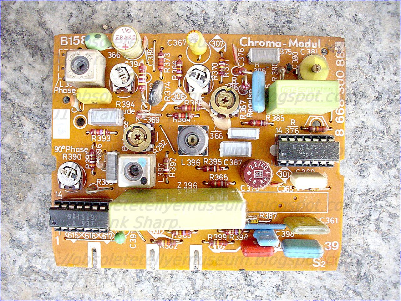

- TUNER 8 668 810 930
- BILD-ZF-MODUL IF UNIT 8 668 810 899 TDA440 (TELEFUNKEN)
- NF MODUL (AF AMPL) 8 668 301 950
- HORIZONTAL OSZILLATOR (SYNCHR) 8 668 300 897 TBA920
- LUMINANZ MODUL (LUMINANCE) 8 668 300 889 TBA396
- CHROMA MODUL 8 668 300 882
- RGB-MODUL 8 668 301 325
- SPANNUNGS MODUL (SEC SUPPLY) 8 668 301 316
- STEUER MODUL (SMPS UNIT) 8 668 301 321 S2530 TOSHIBA
- SSVD-MODUL 8 668 302 260
- HORIZONTAL ENDSTUFEN MODUL 8 668 301 338 BU415 TELEFUNKEN
CRT TV EHT VOLTAGE MULTIPLIER - KASKADE COCKCROFT-WALTON CASCADE CIRCUIT FOR VOLTAGE MULTIPLICATION:

A Cockcroft-Walton cascade circuit comprises an input voltage source and a pumping and storage circuit with a series array of capacitors with pumping and storage portions of the circuit being interconnected by silicon rectifiers, constructed and arranged so that at least the capacitor nearest the voltage source, and preferably one or more of the next adjacent capacitors in the series array, have lower tendency to internally discharge than the capacitors in the array more remote from the voltage source.
1. An improved voltage multiplying circuit comprising,
2. An improved voltage multiplying circuit in accordance with claim 1 wherein said first pumping capacitor is a self-healing impregnated capacitor which is impregnated with a high voltage impregnant.
3. An improved voltage multiplying circuit in accordance with claim 1 wherein said first pumping capacitor comprises a foil capacitor.
Description:
BACKGROUND OF THE INVENTION
The invention relates in general to Cockcroft-Walton cascade circuits for voltage multiplication and more particularly to such circuits with a pumping circuit and a storage circuit composed of capacitors connected in series, said pumping circuits and storage circuit being linked with one another by a rectifier circuit whose rectifiers are preferably silicon rectifiers, especially for a switching arrangement sensitive to internal discharges of capacitors, and more especially a switching arrangement containing transistors, and especially an image tube switching arrangement.
Voltage multiplication cascades composed of capacitors and rectifiers are used to produce high D.C. voltages from sinusoidal or pulsed alternating voltages. All known voltage multiplication cascades and voltage multipliers are designed to be capacitance-symmetrical, i.e., all capacitors used have the same capacitance. If U for example is the maximum value of an applied alternating voltage, the input capacitor connected directly to the alternating voltage source is charged to a D.C. voltage with a value U, while all other capacitors are charged to the value of 2U. Therefore, a total voltage can be obtained from the series-connected capacitors of a capacitor array.
In voltage multipliers, internal resistance is highly significant. In order to obtain high load currents on the D.C. side, the emphasis in the prior art has been on constructing voltage multipliers with internal resistances that are as low as possible.
Internal resistance of voltage multipliers can be reduced by increasing the capacitances of the individual capacitors by equal amounts. However, the critical significance of size of the assembly in the practical application of a voltage multiplier, limits the extent to which capacitance of the individual capacitors can be increased as a practical matter.
In television sets, especially color television sets, voltage multiplication cascades are required whose internal resistance is generally 400 to 500 kOhms. Thus far, it has been possible to achieve this low internal resistance with small dimensions only by using silicon diodes as rectifiers and metallized film capacitors as the capacitors.
When silicon rectifiers are used to achieve low internal resistance, their low forward resistance produces high peak currents and therefore leads to problems involving the pulse resistance of the capacitors. Metallized film capacitors are used because of space requirements, i.e., in order to ensure that the assembly will have the smallest possible dimensions, and also for cost reasons. These film capacitors have a self-healing effect, in which the damage caused to the capacitor by partial evaporation of the metal coating around the point of puncture (pinhole), which develops as a result of internal spark-overs, is cured again. This selfhealing effect is highly desirable as far as the capacitors themselves are concerned, but is not without its disadvantages as far as the other cirucit components are concerned, especially the silicon rectifiers, the image tubes, and the components which conduct the image tube voltage.
It is therefore an important object of the invention to improve voltage multiplication cascades of the type described above.
It is a further object of the invention to keep the size of the entire assembly small and the internal resistance low.
It is a further object of the invention to increase pulse resistance of the entire circuit.
It is a further object of the invention to avoid the above-described disadvantageous effects on adjacent elements.
It is a further object of the invention to achieve multiples of the foregoing objects and preferably all of them consistent with each other.
SUMMARY OF THE INVENTION
In accordance with the invention, the foregoing objects are met by making at least one of the capacitors in the pumping circuit, preferably including the one which is adjacent to the input voltage source, one which is less prone to internal discharges than any of the individual capacitors in the storage circuit.
The Cockcroft-Walton cascade circuit is not provided with identical capacitors. Instead, the individual capacitors are arranged according to their loads and designed in such a way that a higher pulse resistance is attained only in certain capacitors. It can be shown that the load produced by the voltage in all the capacitors in the multiplication circuit is approximately the same. But the pulse currents of the capacitors as well as their forward flow angles are different. In particular, the capacitors of the pumping circuit are subjected to very high loads in a pulsed mode. In the voltage multiplication cascade according to the invention, these capacitors are arranged so that they exhibit fewer internal discharges than the capacitors in the storage circuit.
The external dimensions of the entire assembly would be unacceptably large if one constructed the entire switching arrangement using such capacitors.
The voltage multiplication cascade according to the invention also makes it possible to construct a reliably operating

arrangement which has no tendency toward spark-overs, consistent with satisfactory internal resistance of the voltage multiplication cascade and small dimensions of the entire assembly. This avoids the above cited disadvantages with respect to the particularly sensitive components in the rest of the circuit and makes it possible to design voltage multiplication cascades with silicon rectifiers, which are characterized by long lifetimes. Hence, a voltage multiplication cascade has been developed particularly for image tube circuits in television sets, especially color television sets, and this cascade satisfies the highest requirements in addition to having an average lifetime which in every case is greater than that of the television set.
A further aspect of the invention is that at least one of the capacitors that are less prone to internal discharges is a capacitor which is impregnated with a high-voltage impregnating substance, especially a high-voltage oil such as polybutene or silicone oil, or mixtures thereof. In contrast to capacitors made of metallized film which have not been impregnated, this allows the discharge frequency due to internal discharges or spark-overs to be reduced by a factor of 10 to 100.
According to a further important aspect of the invention, at least one of the capacitors that are less prone to internal discharges is either a foil capacitor or a self-healing capacitor. In addition, the capacitor in the pumping circuit which is adjacent to the voltage source input can be a foil capacitor which has been impregnated in the manner described above, while the next capacitor in the pumping circuit is a self-healing capacitor impregnated in the same fashion.
Other objects, features and advantages of the invention will be apparent from the following detailed description of preferred embodiments, taken in connection with the accompanying drawing, the single FIGURE of which:
BRIEF DESCRIPTION OF THE DRAWING
is a schematic diagram of a circuit made according to a preferred embodiment of the invention.
DETAILED DESCRIPTION OF PREFERRED EMBODIMENTS
The voltage multiplier comprises capacitors C1 to C5 and rectifiers D1 to D5 connected in a cascade. An alternating voltage source UE is connected to terminals 1 and 2, said voltage source supplying for example a pulsed alternating voltage. Capacitors C1 and C2 form the pumping circuit while capacitors C3, C4 and C5 form the storage circuit.
In the steady state, capacitor C1 is charged to the maximum value of the alternating voltage UE as are the other capacitors C2 to C5. The desired high D.C. voltage UA is picked off at terminals 3 and 4, said D.C. voltage being composed of the D.C. voltages from capacitors C3 to C5. Terminal 3 and terminal 2 are connected to one pole of the alternating voltage source UE feeding the circuit, which can be at ground potential. In the circuit described here, a D.C. voltage UA can be picked off whose voltage value is approximately 3 times the maximum value of the pulsed alternating voltage UE. By using more than five capacitors, a correspondingly higher D.C. voltage can be obtained.

The individual capacitors are discharged by disconnecting D.C. voltage UA. However, they are constantly being recharged by the electrical energy supplied by the alternating voltage source UE, so that the voltage multiplier can be continuously charged on the output side.
According to the invention, in this preferred embodiment, capacitor C1 and/or C2 in the pumping circuit are designed so that they have a lower tendency toward internal discharges than any of the individual capacitors C3, C4 and C5 in the storage circuit.
It is evident that those skilled in the art, once given the benefit of the foregoing disclosure, may now make numerous other uses and modifications of, and departures from the specific embodiments described herein without departing from the inventive concepts. Consequently, the invention is to be construed as embracing each and every novel feature and novel combination of features present in, or possessed by, the apparatus and techniques herein disclosed and limited solely by the scope and spirit of the appended claims.
Inventors:Petrick, Paul (Landshut, DT)
Schwedler, Hans-peter (Landshut, DT)
Holzer, Alfred (Schonbrunn, DT)
ERNST ROEDERSTEIN SPEZIALFABRIK
US Patent References:
3714528 ELECTRICAL CAPACITOR WITH FILM-PAPER DIELECTRIC 1973-01-30 Vail
3699410 SELF-HEALING ELECTRICAL CONDENSER 1972-10-17 Maylandt
3463992 ELECTRICAL CAPACITOR SYSTEMS HAVING LONG-TERM STORAGE CHARACTERISTICS 1969-08-26 Solberg
3457478 WOUND FILM CAPACITORS 1969-07-22 Lehrer
3363156 Capacitor with a polyolefin dielectric 1968-01-09 Cox
2213199 Voltage multiplier 1940-09-03 Bouwers et al.
SIEMENS BILDMEISTER FC524 (7 667 279) CHASSIS FM100 Controlled power supply for a television receiver equipped with remote control:BLAUPUNKT SWITCH MODE POWER SUPPLY.Blaupunkt-Werke GmbH (Hildesheim, DT)
A single isolation transformer supplies both the remote control receiver and the television receiver. A pulse generator such as a blocking oscillator which energizes the primary winding of the isolation transformer has its pulse width controlled in response to the loading of the circuit of the secondary winding of the isolation transformer, as measured by the voltage across a resistor in the circuit of a primary winding. This measuring resistor is interposed between the emitter of the switching transistor of the blocking oscillator and the receiver chassis. A transistor switching circuit for cutting off the low voltage supply to the scanning circuit oscillators of the television receiver is responsive to the output of the remote control receiver, to a signal from an operating control of the television receiver, and to an indication of overcurrent in the picture tube, independently.
an on-off switch for connecting and disconnecting the television receiver and its power supply circuit respectively to and from the electricity supply mains;
pulse generating means arranged for energization through said on-off switch;
an isolation transformer having its primary winding supplied with the output of said pulse generating means;
a power conversion circuit connected to the secondary winding of said isolation transformer for energization thereby, for supplying an operating voltage for the scanning circuits of the television receiver and for supplying a plurality of other voltages to said receiver, at least one of which other voltages is also supplied to said scanning circuits;
means for reducing energy transfer through said pulse generating means to said isolation transformer when said television receiver is in the stand-by condition.
2. A power supply circuit as defined in claim 1, in which said pulse generating means includes rectifying means energized through said on-off switch for supplying direct current for energization of said pulse generating means. 3. A power supply circuit as defined in claim 2, in which said energy transfer reducing means includes means for varying the width (duration) of pulses generated by said pulse generating means in response to the extent of loading of the secondary circuit of said isolating transformer as measured in the primary circuit of said transformer. 4. A power supply circuit as defined in claim 2, in which said pulse generating means includes a blocking oscillator and said energy transfer reducing means includes means for reducing the width (duration) of the pulses generated by said blocking oscillator. 5. A power supply circuit as defined in claim 4, in which said blocking oscillator includes a switching transistor (5) and a load measuring resistor (7) interposed in a connection between the emitter of said switching transistor and the receiver chassis, and in which said pulse width reducing means is responsive to the voltage drop across said load measuring resistor. 6. A power supply circuit as defined in claim 5, in which said pulse width reducing means includes a controllable resistance (10) in the circuit of said blocking oscillator controlled in response to the voltage drop across said load measuring resistor. 7. A power supply circuit as defined in claim 1, in which said operating voltage connected and disconnected to said scanning circuits by said controlled switching means is the low voltage supply voltage (U 3') of the line scan and picture scan oscillators of the television receiver and in which said controlled switching means is controlled so as to switch off said low voltage supply voltage to put the television receiver in the stand-by condition. 8. A power supply circuit as defined in claim 7, in which said controlled switching means includes a first switching transistor (15) at the collector of which there is applied a direct current supply voltage (U 3) energized through said isolating transformer and a second switching transistor (24) for controllably short-circuiting the base bias of said first switching transistor, whereby a stabilized low voltage (U 3') exists at the emitter of said first switching transistor (15) when a positive signal is supplied from an operating control of the television receiver or from said remote control receiver to the base of said second switching transistor (24). 9. A power supply circuit as defined in claim 7, in which said controlled switching means is responsive independently to an overcurrent condition in the picture tube for switching off said low voltage supply voltage (U 3') in response to said overcurrent condition.
Description:

In recent times television receivers have frequently been provided with ultrasonic remote control devices for the purpose of offering easier control. As more and more television receivers are utilized in combination with additional equipment, it becomes increasingly necessary to connect the receivers only indirectly to the electric power mains (house wiring). In a known advantageous solution of this problem, a power supply unit includes an isolating transformer which is wired up with a blocking oscillator in the primary circuit. The blocking oscillator is supplied with a d-c voltage which is obtained by rectification of the supply voltage. Compared to the isolating transformers which are directly mains-operated, these so-called switch-mode power supply units have the advantage that they can be made in considerably smaller size, as they are operated at a significantly higher frequency, and the further advantage that they require less expensive means for rectification.
It is necessary to supply television receivers equipped with ultrasonic remote control with the possibility for a stand-by operation in which only the ultransonic receiver is supplied with power and, in some cases, also the heating current for the picture tube. Usually a separate power supply unit is provided for the ultrasonic receiver and the heating of the picture tube, a unit that includes an isolating transformer of its own, the primary winding of which is directly mains-fed. Upon transition from normal operation to stand-by operation, the power supply unit of the blocking osciallator is switched off, so that the television receiver receives only the relatively small quantity of energy required for the ultrasonic receiver and, in some cases, also for the heating of the picture tube.
Because of the required second isolating transformer, this known circuit has the disadvantages that it requires both greater space and greater expenditure.
It is the object of the present invention to develop a simplified power supply unit which does not have the above-mentioned disadvantages.
SUMMARY OF THE INVENTION
Briefly, the television receiver and the ultrasonic receiver are connected to the same isolating transformer; means for the switching from normal operation to stand-by operation and vice versa are placed in the secondary circuit of the isolating transformer, and means are arranged in the primary circuits of the isolating transformer for reducing the amount of energy made available for stand-by operation purposes.
The main advantages of the present invention are that no separate isolating transformer is required for supplying the current during the stand-by operation, and that, during the stand-by operation, it is nevertheless only the power required for this operation which is consumed.
An advantageous embodiment of the presen
t invention obtains reduction of the energy quantum transmitted through the power supply during stand-by by reduction of the pulse width of the pulses generated by the blocking oscillator. Another advantageous embodiment of the present invention utilizes measurement in the primary circuit of the isolating transformer of variation in load occurring in the secondary circuit as a control variable for determining the pulse width.
A further advantageous embodiment of the present invention obtains the control variable for the pulse width across a measuring resistor interposed in the connection of the emitter of the switching transistor of the blocking oscillator to the chassis.
Still another advantageous embodiment of the present invention provides that the voltage drop across the measuring resistor controls a controllable resistor.
The advantageous embodiments described above offer highly simple and advantageous possibilities for measuring the variation in load upon switching between normal and stand-by operation, as well as for the consequent control of the energy transmitted via the isolating transformer.
The possibility of a simple and inexpensive switching between normal and stand-by operation is achieved by effecting the switching between normal and stand-by operation by means of switching on or switching off, respectively, the low voltage supply of the line scan oscillator, and, especially, by a first switching transistor which short-circuits the base bias of a second switching transistor at the collector of which a direct current supply voltage is present and at the emitter of which a stabilized low voltage exists, when a positive signal is supplied from the operating control of the television receiver or from the remote control receiver to the base of the first switching transistor.
The circuit arrangements just mentioned offer the advantage that they may simultaneously be utilized as a protective circuit. This is achieved by a switching-off device for the low voltage which can also be triggered at any time by a signal built up by overcurrent in the picture tube.
The invention is further described by way of illustrative example by reference to the annexed drawings in which:
FIG. 1 is a circuit diagram, partly in block form, of an embodiment of the invention;
FIG. 2 is a circuit diagram of one form of means for interrupting the power to the picture circuits in the stand-by condition in connection with the circuit of FIG. 1, and
FIG. 3 is a circuit diagram of one way of controlling the pulse width of the blocking oscillator 4 in response to the switching circuit 8 in the circuit of FIG. 1.
DESCRIPTION OF THE PREFERRED EMBODIMENT
 An on-off power switch 2 of the television receiver is connected to the supply terminals 1, providing a primary operating control for the receiver. Consquently, the supply voltage is also present at the output of the operating control 2 when the television receiver is turned on thereby, and arrives at a rectifying stage 3 comprising means for rectifying and smoothing the supply current as well as for suppressing interference. A d-c voltage, feeding a blocking oscillator stage 4, is present at the output of the recifying stage 3. The main part of the blocking oscillator 4, symbolically represented in FIG. 1 by a fragmentary circuit diagram, is a switching transistor 5, in the load circuit of which the primary winding of an isolating tranformer 6 is placed. A measuring resistor 7 is connected between the emitter of the switching transistor 5 and the chassis, across which measuring resistor a voltage is taken and applied to a load-dependent control circuit 8. The voltage taken at the measuring resistor 7 is fed via a resistor 9 to the base of a transistor 10 which serves as a controllable load for the blocking oscillator 4. A resistor 11 and a capacitor 12, each of which is connected to chassis with its other terminal, are also connected to the base of the transistor 10. The emitter of transistor 10 is connected to chassis, while the collector of the transistor 10 is connected back to the blocking oscillator stage 4. In the secondary circuit of the isolating transformer 6, a d-c voltage supply stage or power conversion circuit 13 is placed, substantially consisting of a rectifying circuit 14, which, in the example shown, is provided with six outputs at which the voltages U 1 to U 5 can be taken off with respect to the sixth output connected to the chassis. At the terminal U 3, there is, in addition, a branch feeding both the collector-to-emitter path of the transistor 15 and also, through a resistor 16, the collector-to-emitter path of the transistor 15a. The emitter of the transistor 15a is directly connected to the base of transistor 15. The emitter of the transistor 15 is connected to chassis via a series connection of a resistor 17, a potentiometer 18, and a further resistor 19. The tap of the potentiometer 18 is connected to the base of a further transistor 20. The transistor 20 is connected to chassis by means of its emitter via a Zener diode 21, the collector of the transistor 20 controlling the base of the transistor 15a. The emitter of the transistor 20 is connected to the emitter of the transistor 15 via a resistor 22. A terminal for tapping off the voltage U 3' is connected to the emitter of the transistor 15.
 The base of the transistor 15a is connected to a switching stage 23 responsive to a remote control ultrasonic receiver by a conductor leading to the collector of a switching transistor 24 which is connected to chassis via its emitter. The base of the switching transistor 24 is connected to an input terminal 28 leading into the television receiver via two resistors 25, 26 and a capacitor 27 connected in series, that input terminal 28 passing on switching signals from the receiver to the switching transistor 24, as will be explained in more detail below.
The cathode of a diode 29, which is connected to chassis via its anode, is connected to the junction point of the resistor 26 and the capacitor 27. The junction point of the two resistors 25, 26 is connected to chassis via a capacitor 30. The base of the switching transistor 24 is connected to chassis via a resistor 31. Furthermore, that base electrode is also connected to a terminal 32 to which an electrical switching signal is applied which is either built up in response to an ultrasonic signal received by the remote control receiver 32' or is supplied from an operating control of the television receiver. At the terminal 32, the switching transistor 24 receives the signal containing the information whether the television receiver is to work in the normal operating condition, i.e. to receive and process the sound and video signals, or in the stand-by condition in which it is substantially only the ultrasonic receiver that is supplied with current.
When a positive signal arrives at the base of the switching transistor 24, the latter becomes conductive, and causes chassis potential to be present at the base of transistor 15a. The transistor 15 is thereby blocked, and there is no longer any voltage at the terminal U 3'. Since the voltage U 3' serves as an operating voltage for the line and picture scan oscillator, the deflecting stages of the receiver cannot work and no high voltage and other related supply voltages are generated at the line circuit transformer. In consequence, by means illustrated diagrammatically in
 FIG. 2, the electric circuits connected to the terminals U 1 to U 3 are interrupted. The voltages U 4 and U 5 serve for supplying the ultrasonic receiver, i.e. they are required for the stand-by operation.
 In case no counteracting means should be provided for, the variation in load would cause a voltage rise in the secondary circuit of the isolating transformer 6, which effect is, of course, not desired. Therefore, a measuring resistor is connected in the primary circuit in the emitter line of the switching transistor 5 of the blocking oscillator 6, the variation in load in the secondary circuit appearing at the measuring resistor 7 as a current variation. The current change thus produced, causes a variation in the base bias of the transistor 10, the capacitor 12 having an integrating effect to avoid undesired effects due to interference pulses and abrupt load fluctuations.
The change of the working point of the transistor 10 causes a change in the pulse width in the blocking oscillator stage 4, as more fully shown in FIG. 3, so that the energy quantum transmitted via the isolating transformer 6 is such that the required voltages are present in the secondary circuit. It should also be mentioned that the load-dependent switch 8 and the circuit of FIG. 3 are represented only by way of illustration and that many circuit arrangements may be devised by straight-forward application of known principles for controlling the pulse width.
Using the circuit diagram according to FIG. 3 it is possible in a simple manner to control the pulse width of the blocking oscillator 4 in response to the switching circuit 8.
According to the circuit diagram of FIG. 2 the terminal U1 is connected to a line scan oscillator circuit 40, the terminal U2 to a picture scan oscillator circuit 41 and the terminal U3 to a circuit 42 for a sound output stage. The circuits 40, 41, 42 get their operating voltage from the terminal U3'. If the operating voltage U3' is zero, the circuits 40, 41, 42 are interrupted. In this case the voltages at the terminals U1, U2, U3 remain.
The blocking oscillator stage 4 shown in detail in FIG. 3 incorporates an externally triggered blocking oscillator arranged to be triggered through an oscillator operating preferably at the line scanning frequency, which is to say its wave form is not particularly critical and it should be provided with means to keep it in step with the line scanning frequency, as is known to be desirable. The transistors 51 and 52 of the triggered output stage of the blocking oscillator circuit could be regarded as constituting a differential amplifier the inputs of which are defined by the base connections of the respective transistors 51 and 52. The input voltage applied to the base connection of transistor 52 is the Zener voltage of the Zener diode 53, thus a constant reference voltage. The operating voltage for the transistors 51 and 52 and for the Zener diode 53 is obtained from the supply voltage UB, which is to say from the rectifier 3. The diode 67 protects the transistor 52, for example at the time of the apparatus being switched on, against damage from an excessively high emitter-base blocking voltage. The capacitor 65 prevents undesired oscillation of the circuit of transistors 51 and 52, which could give rise to undesired disturbances.
At the base of the transistor 51, there is present as input voltage for the circuit a composite voltage that is the sum of three voltages. These are, first, the line scan frequency trigger voltage coupled through the capacitor 63; second, a bias voltage dependent upon the loading of the blocking oscillator stage resulting from the load on the secondary of the transformer 6, but detected by the voltage across the resistor 7 and actually controlled by the load-sensitive control circuit 8, and, third, a regulating voltage applied at the terminal 71 of the resistor 70, which regulating voltage is proportional to the voltage of the secondary winding of the transformer 6 and can accordingly be provided by one or another of the output circuits of the rectifier 14 of FIG. 1 or by a separate winding of the transformer 6 and a separate rectifier element connected in circuit therewith. This regulating voltage and the control voltage provided by the control circuit 8 are applied to the resistor 61 which completes the circuit for both of these bias voltages and their combined effect constitutes the bias voltage for the transistor 51 which determines its working point.
The circuit of the transistors 51 and 52 operates as an overdriven differential amplifier. When the trigger voltage exceeds the threshold determined by the base voltage of the transistor 51, the circuit produces an approximately rectangular output voltage pulse of constant amplitude. Since the trigger voltage is recurrent, the result is a periodic succession of rectangular output voltage pulses, but the duration or pulse width of these pulses depends upon the loading and the output voltage of the stage. The output voltage of the circuit constituted by the transistors 51 and 52 comes from the emitter connection of the transistor 52 and is furnished to the switching transistor 5, preferably through a driver stage 54, such as a transformer or another transistor stage for better matching of the circuit impedances. Of course, the collector circuit of the transistor 5 includes the primary winding of the transformer 6 of FIG. 1.
SIEMENS BILDMEISTER FC524 (7 667 279) CHASSIS FM100 Television receiver with an automatic station finding arrangement:
MOTOROLA TUNING MEMORY / MEMOTRONIC SYSTEM TECHNOLOGY 8 668 301 411.In a radio or television receiver containing an automatic station finder with a digital counter, a clock generator, and a digital-to-analog converter forming the tuning voltage for the varactors, a recall memory consisting of two series-connected parallel memories is connected in parallel with the digital counter. At a stop signal from the
1. A receiver having automatic station finding capability, comprising:
means for tuning said receiver in response to an applied voltage;
a controllable pulse generator;
means for starting said pulse generator;
circulating counter means having parallel inputs and outputs, a stepping input and a set input, said stepping input connected to and responsive to pulses from said pulse generator for providing a variable digital output;
digital-to-analog convert
means for sensing a received signal and for providing a stop signal to the pulse generator in response thereto, whereby said generator stops providing pulses and the analog voltage remains constant keeping the receiver tuned to the received signal;
memory means having parallel inputs connected to the parallel outputs of said counter means and parallel outputs connected to the parallel inputs of said counter means;
means associated with said memory means for causing the memory means to store a particular digital output from said counter means; and
means associated with the set input of said counter means for selectively causing the digital signal at the counter input to be transferred to the counter output.
3. A receiver as described in claim 2, wherein each of said parallel memories comprises a plurality of semiconductor voltage flip-flops.
4. A receiver as described in claim 2, wherein the two series connected parallel memories are incorporated in an integrated circuit module with the counter means.
5. A receiver as described in claim 2, wherein the transfer input of the first parallel memory is also connected to the means associated with the set input of the counter means.
6. A receiver as described in claim 1, additionally comprising:
an additional memory means having parallel inputs and outputs;
means for connecting the inputs of said additional memory means to the counter means output and the outputs of said additional memory means to the counter inputs;
means for causing said additional memory means to store a digital output; and
means for transferring the stored digital output to the counter means input through the connecting means.
7. A receiver as described in claim 6, additionally comprising gate means disposed at the outputs of the memory means and the additional memory means for selectively connecting either the additional memory means or the memory means to the input of the counter.
8. A receiver as described in claim 6, wherein the additional memory means comprises a plurality of memories and the connecting means comprises a plurality of station switches corresponding in number to the number of additional memories.
9. A receiver as described in claim 1, wherein each memory means comprises a number of flip-flops corresponding to the number of digits to be stored.
Description:
The p
resent invention relates to a radio or television receiver with an automatic station finding arrangement which contains a pulse generator, a circulating counter formed from semiconductor counting flip-flops and having parallel inputs, a digital-to-analog converter converting the count of the counter to a tuning voltage, and a start-stop circuit acting on the flow of counting pulses and controlled over a start and at least one stop line, and with a parallel memory connected between the parallel outputs and parallel inputs of the counter.
Such a radio receiver is known from, e.g., the journal "Funkschau 1971", pp. 535 to 538 and 587 to 589. With the aid of the free-running pulse generator, the up-counter, and the digital-to-analog converter, the automatic station finding arrangement generates a sawtoothlike tuning voltage for the varactors contained as frequency-setting tuning elements in the resonant circuits of the receiver's radio-frequency portion. If a transmitter is received which meets the receiving criteria set in the receiver, the pulse generator is stopped so that the tuning voltage now remains constant until the operator continues the automatic station finding operation by actuating a start switch.
I t is frequently desirable to tune in once again the station at which the start switch for automatic station finding was actuated last - either for comparison or because of the more interesting program. To do this in the case of a receiver with provision for unidirectional automatic station search, the entire search range must be scanned once or several times by repeatedly actuating the start switch, depending on whether the desired station is detected immediately or not.
It is the object of the invention to provide measures for a receiver of the kind referred to by way of introduction which permit the transmitter received before the actuation of the start switch to be found again with a high degree of safety by simple manipulation.
The invention is characterized in that the parallel memory consists of two series-connected parallel memories having one transfer input each, that the transfer input of the (first) parallel memory, whose parallel inputs are connected to the parallel outputs of the counter, are connected directly or indirectly to the stop line, that the transfer input of the (second) parallel memory, whose parallel outputs are connected to the parallel inputs of the counter, is connected directly or indirectly to the start line, that the counter has a set input for through-connecting the parallel inputs of the counter to the flip-flops of the counter, and that a recall switch is connected to the set input of the counter.
Particularly advantageously, the memory locations of the two series-connected parallel memories are storage flip-flops using semiconductor technology. In that case it is possible to arrange the counter and the parallel memories on a common chip of an integrated-circuit module. Such a module has only two terminals more than a module formed by the counter only.
The measures characterized by the invention thus require, aside from an additional recall switch, no additional space and involve nearly no additional expense. To recall the station previously tuned in it is only necessary to depress a button, for example, whereby the receiver is safely tuned to the station's carrier wave even if at the instant of the depression the local received field strength is temporarily too low for sufficient reception.
The invention will now be described in more detail with reference to the accompanying drawing, showing, by way of example, two embodiments of the invention, and wherein:
FIG. 1 is a block diagram showing the radio- and intermediate-frequency portions of a receiver with an automatic station finding arrangement and a recall arrangement;
FIG. 2 shows diagrams a to g explaining the operation of the recall storage, and
FIG. 3 shows a receiver similar to the one of FIG. 1 in which the automatic station finding counter and the recall memories are arranged together on the chip of an integrated-circuit module.
The receivers shown in the block diagrams of FIGS. 1 and 3 have a radio-frequency-receiving section 1, an intermediate-frequency amplif ier 2, and a demodulator section 3, to whose output 4 are connected the arrangements processing the modulation frequency. The tunable resonant circuits of the radio-frequency section contain varactors as tuning elements. Connected to the radio-frequency section is an automatic station finding arrangement in which a digital-to-analog converter 5 generates from the count of a digital counter 7, which receives signals at a stepping input T and advances at the rate of a pulse generator 6, a nearly sawtooth-shaped tuning voltage for the varactors. With a sufficient received field strength at the antenna 8 of the receiver a signal is formed in the demodulator section 3 which signal can be used as stop signal 9 to change the state of a start-stop circuit 10 which may be a flip flop. In the "stop" state the start-stop circuit interrupts the pulse generation or the pulse flow in the pulse generator so that the receiver remains tuned to the station being received. By operating a start-button switch 11 a start signal 12 is generated in the receiver which signal places the start-stop circuit in the "automatic station finding" state and thus continues the automatic station finding operation until next station meeting the receiver's receiving requirements is received.
In the embodiment of FIG. 1, two series-connected parallel memories 15 and 16 are connected, respectively, over two groups of lines 13 and 14 consisting of n lines each, between the n outputs Q 11 to Q n1 and the parallel inputs A 11 to A n1 of the digital counter 7 containing n counting flip-flops. Each parallel memory contains n storage flip-flops and, besides the parallel bit inputs and outputs B and X, a transfer input S. If a transfer signal appears at the transfer input, the parallel memory records the bit word applied its parallel inputs B 1 to B n , which erases the previously entered bit word and now, in turn, appears at the memory outputs X 1 to X n .
The transfer input S of the parallel memory 15, whose parallel inputs are connected over the group of lines 13 to the outputs of the counter 7, is connected to the stop line 17, while the transfer input S of the parallel memory 16, whose parallel outputs are connected over the group of lines 14 to the parallel inputs of the counter 7, is connected to the start line 18.
Connected to a set input P of the digital counters 7 is a switch 19 whose operation generates a set signal. The set signal sets the counter to a count which is equal to the bit word at the parallel inputs A 1 to A n of the counter. At the same time, the set signal acts over the line 20 and via an OR circuit provided for isolation on the transfer input S of the first parallel memory 15.
The diagrams a to g of FIG. 2 explain the operation of the automatic station finding arrangement in conjunction with the recall memories. In diagram a each of the blocks II, III, etc. represents the bit word for a count of the digital counter 7. The blocks in the diagrams b and c are the bit words which are stored in the parallel memories 15 and 16 and can be taken off the latter's parallel outputs, the blocks with equal Roman numerals (e.g. V) representing equal bit words. The diagram d shows the counting pulses 22 for the digital counter 7, the diagram e the stop pulses 9, the diagram f the start pulses 12, and the diagram g the set pulse 23 triggered by the recall switch 19.
The respective count from which the digital-to-analog converter 5 forms the tuning voltage for the varactors is applied simultaneously to the input of the digital-to-analog converter and, as a bit word (e.g. II, III, IV . . . , diagram a), to the input of the first parallel memory 15. At the occurence of a stop signal 9 during the automatic station finding operation, the stop signal 9 acts as a transfer signal on the first par
 allel memory 15, and the count (e.g. V, diagram a) at which the stop pulse (e.g. 9a) was generated is entered into the first parallel memory 15 (V in diagram b). At the next start pulse 12a triggered via the start-button switch 11 the automatic station finding operation begins anew, starting from the instantaneous count (e.g. V, diagram a) of the counter. The start signal (12a in diagram f) acts as a transfer signal on the transfer input S of the second parallel memory 16, whereby the second parallel memory takes over the bit word (e.g. V) of the first. The next stop signal (e.g. 9b, diagram e) at a new count (e.g. VIII, diagram a) stops the automatic station search and enters the new count as a bit word (e.g. VIII, diagram b) into the first parallel memory 15.
If the operator operates the recall switch 19 so as to recall the setting to the previously received station, the set pulse 23 triggered by the recall switch sets the counter 7 to the count (e.g. V, diagram a) of the bit word (e.g. V, diagram c) stored in the second parallel memory 16, and the newly set count is entered into the first parallel memory 15 (e.g. V, diagram b). The next start signal (e.g. 12b, diagram f) initiates the automatic station finding operation as described.
In the embodiment of FIG. 3, the two series-connected parallel memories 15 and 16 are incorporated on the chip of an integrated-circuit module 25 which also comprises the circulating digital counter 7 and, for exam ple, the circuit 26 of a station memory device. The station memory device has the memory inputs D 1 to D n and the memory outputs Y 1 to Y n of its circuit 26 connected in parallel with the digital counter 7 in the same manner as the recall memory consisting of the two series-connected parallel memories 15 and 16. Therefore, gate circuits 27 and 28 are inserted between the parallel outputs of these memories and the parallel inputs A 1 to A n of the digital counter. The gate circuit 27 between the recall memory and the counter is opened by the set signal of the recall switch 19. The gate circuit 28 between the station memory and the counter is opened by the set signal of a switch 29 for calling the bit word of a station preselected by the station buttons 30. In front of the set input 8 of the digital counter the two set signals are separated from one another in an OR circuit 31.
In the embodiment of FIG. 3, the start-stop circuit 10 is designed in the manner of a flip-flop and can assume a "stop" state and an "automatic station finding" state. The transfer inputs S of the recall memory's parallel memories 15 and 16 are connected via the lines 32 and 33 to the outputs of the start-stop circuit. Since the signals at the outputs of the start-stop circuit are continuous signals, the lines 32 and 33 to the transfer inputs include pulse shapers 34 and 35, respectively.
In embodiments corresponding to FIG. 3 and having no station memory device, besides the circuit 26, the gate circuits 27 and 28 and the OR circuit 31 are omitted.
Such a radio receiver is known from, e.g., the journal "Funkschau 1971", pp. 535 to 538 and 587 to 589. With the aid of the free-running pulse generator, the up-counter, and the digital-to-analog converter, the automatic station finding arrangement generates a sawtoothlike tuning voltage for the varactors contained as frequency-setting tuning elements in the resonant circuits of the receiver's radio-frequency portion. If a transmitter is received which meets the receiving criteria set in the receiver, the pulse generator is stopped so that the tuning voltage now remains constant until the operator continues the automatic station finding operation by actuating a start switch.
I
t is frequently desirable to tune in once again the station at which the start switch for automatic station finding was actuated last - either for comparison or because of the more interesting program. To do this in the case of a receiver with provision for unidirectional automatic station search, the entire search range must be scanned once or several times by repeatedly actuating the start switch, depending on whether the desired station is detected immediately or not. It is the object of the invention to provide measures for a receiver of the kind referred to by way of introduction which permit the transmitter received before the actuation of the start switch to be found again with a high degree of safety by simple manipulation.
The invention is characterized in that the parallel memory consists of two series-connected parallel memories having one transfer input each, that the transfer input of the (first) parallel memory, whose parallel inputs are connected to the parallel outputs of the counter, are connected directly or indirectly to the stop line, that the transfer input of the (second) parallel memory, whose parallel outputs are connected to the parallel inputs of the counter, is connected directly or indirectly to the start line, that the counter has a set input for through-connecting the parallel inputs of the counter to the flip-flops of the counter, and that a recall switch is connected to the set input of the counter.
Particularly advantageously, the memory locations of the two series-connected parallel memories are storage flip-flops using semiconductor technology. In that case it is possible to arrange the counter and the parallel memories on a common chip of an integrated-circuit module. Such a module has only two terminals more than a module formed by the counter only.
The measures characterized by the invention thus require, aside from an additional recall switch, no additional space and involve nearly no additional expense. To recall the station previously tuned in it is only necessary to depress a button, for example, whereby the receiver is safely tuned to the station's carrier wave even if at the instant of the depression the local received field strength is temporarily too low for sufficient reception.
The invention will now be described in more detail with reference to the accompanying drawing, showing, by way of example, two embodiments of the invention, and wherein:
FIG. 1 is a block diagram showing the radio- and intermediate-frequency portions of a receiver with an automatic station finding arrangement and a recall arrangement;
FIG. 2 shows diagrams a to g explaining the operation of the recall storage, and
FIG. 3 shows a receiver similar to the one of FIG. 1 in which the automatic station finding counter and the recall memories are arranged together on the chip of an integrated-circuit module.
The receivers shown in the block diagrams of FIGS. 1 and 3 have a radio-frequency-receiving section 1, an intermediate-frequency amplif
 ier 2, and a demodulator section 3, to whose output 4 are connected the arrangements processing the modulation frequency. The tunable resonant circuits of the radio-frequency section contain varactors as tuning elements. Connected to the radio-frequency section is an automatic station finding arrangement in which a digital-to-analog converter 5 generates from the count of a digital counter 7, which receives signals at a stepping input T and advances at the rate of a pulse generator 6, a nearly sawtooth-shaped tuning voltage for the varactors. With a sufficient received field strength at the antenna 8 of the receiver a signal is formed in the demodulator section 3 which signal can be used as stop signal 9 to change the state of a start-stop circuit 10 which may be a flip flop. In the "stop" state the start-stop circuit interrupts the pulse generation or the pulse flow in the pulse generator so that the receiver remains tuned to the station being received. By operating a start-button switch 11 a start signal 12 is generated in the receiver which signal places the start-stop circuit in the "automatic station finding" state and thus continues the automatic station finding operation until next station meeting the receiver's receiving requirements is received.
 In the embodiment of FIG. 1, two series-connected parallel memories 15 and 16 are connected, respectively, over two groups of lines 13 and 14 consisting of n lines each, between the n outputs Q 11 to Q n1 and the parallel inputs A 11 to A n1 of the digital counter 7 containing n counting flip-flops. Each parallel memory contains n storage flip-flops and, besides the parallel bit inputs and outputs B and X, a transfer input S. If a transfer signal appears at the transfer input, the parallel memory records the bit word applied its parallel inputs B 1 to B n , which erases the previously entered bit word and now, in turn, appears at the memory outputs X 1 to X n .
The transfer input S of the parallel memory 15, whose parallel inputs are connected over the group of lines 13 to the outputs of the counter 7, is connected to the stop line 17, while the transfer input S of the parallel memory 16, whose parallel outputs are connected over the group of lines 14 to the parallel inputs of the counter 7, is connected to the start line 18.
Connected to a set input P of the digital counters 7 is a switch 19 whose operation generates a set signal. The set signal sets the counter to a count which is equal to the bit word at the parallel inputs A 1 to A n of the counter. At the same time, the set signal acts over the line 20 and via an OR circuit provided for isolation on the transfer input S of the first parallel memory 15.
The diagrams a to g of FIG. 2 explain the operation of the automatic station finding arrangement in conjunction with the recall memories. In diagram a each of the blocks II, III, etc. represents the bit word for a count of the digital counter 7. The blocks in the diagrams b and c are the bit words which are stored in the parallel memories 15 and 16 and can be taken off the latter's parallel outputs, the blocks with equal Roman numerals (e.g. V) representing equal bit words. The diagram d shows the counting pulses 22 for the digital counter 7, the diagram e the stop pulses 9, the diagram f the start pulses 12, and the diagram g the set pulse 23 triggered by the recall switch 19.
The respective count from which the digital-to-analog converter 5 forms the tuning voltage for the varactors is applied simultaneously to the input of the digital-to-analog converter and, as a bit word (e.g. II, III, IV . . . , diagram a), to the input of the first parallel memory 15. At the occurence of a stop signal 9 during the automatic station finding operation, the stop signal 9 acts as a transfer signal on the first par
If the operator operates the recall switch 19 so as to recall the setting to the previously received station, the set pulse 23 triggered by the recall switch sets the counter 7 to the count (e.g. V, diagram a) of the bit word (e.g. V, diagram c) stored in the second parallel memory 16, and the newly set count is entered into the first parallel memory 15 (e.g. V, diagram b). The next start signal (e.g. 12b, diagram f) initiates the automatic station finding operation as described.
In the embodiment of FIG. 3, the two series-connected parallel memories 15 and 16 are incorporated on the chip of an integrated-circuit module 25 which also comprises the circulating digital counter 7 and, for exam
 ple, the circuit 26 of a station memory device. The station memory device has the memory inputs D 1 to D n and the memory outputs Y 1 to Y n of its circuit 26 connected in parallel with the digital counter 7 in the same manner as the recall memory consisting of the two series-connected parallel memories 15 and 16. Therefore, gate circuits 27 and 28 are inserted between the parallel outputs of these memories and the parallel inputs A 1 to A n of the digital counter. The gate circuit 27 between the recall memory and the counter is opened by the set signal of the recall switch 19. The gate circuit 28 between the station memory and the counter is opened by the set signal of a switch 29 for calling the bit word of a station preselected by the station buttons 30. In front of the set input 8 of the digital counter the two set signals are separated from one another in an OR circuit 31.
 In the embodiment of FIG. 3, the start-stop circuit 10 is designed in the manner of a flip-flop and can assume a "stop" state and an "automatic station finding" state. The transfer inputs S of the recall memory's parallel memories 15 and 16 are connected via the lines 32 and 33 to the outputs of the start-stop circuit. Since the signals at the outputs of the start-stop circuit are continuous signals, the lines 32 and 33 to the transfer inputs include pulse shapers 34 and 35, respectively.
In embodiments corresponding to FIG. 3 and having no station memory device, besides the circuit 26, the gate circuits 27 and 28 and the OR circuit 31 are omitted.
MOTOROLA TV ICs DEMODULATION: TBA396


No comments:
Post a Comment
The most important thing to remember about the Comment Rules is this:
The determination of whether any comment is in compliance is at the sole discretion of this blog’s owner.
Comments on this blog may be blocked or deleted at any time.
Fair people are getting fair reply. Spam and useless crap and filthy comments / scrapers / observations goes all directly to My Private HELL without even appearing in public !!!
The fact that a comment is permitted in no way constitutes an endorsement of any view expressed, fact alleged, or link provided in that comment by the administrator of this site.
This means that there may be a delay between the submission and the eventual appearance of your comment.
Requiring blog comments to obey well-defined rules does not infringe on the free speech of commenters.
Resisting the tide of post-modernity may be difficult, but I will attempt it anyway.
Your choice.........Live or DIE.
That indeed is where your liberty lies.
Note: Only a member of this blog may post a comment.